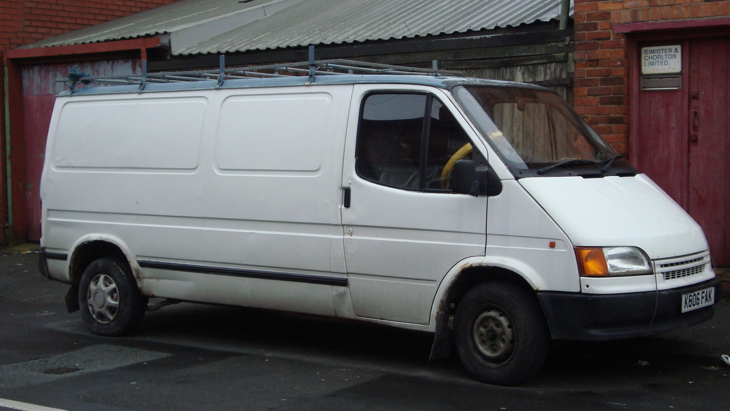
The Ford Transit (1992-1995) uses a revised central fuse and relay assembly under the dashboard. This panel has 24 main fuse positions, additional F1-F4 spare/ABS locations and 20 separate relay sockets marked A-H and I-XII. It differs from the 1986-1992 board although some vehicles from the transition years look very similar.
All 48 original entries are retained below, including blank relay sockets, optional headlamp washing, heated front and rear windscreens, ABS, rear wiper and automatic gearbox circuits. The numbers belong to this exact board style: verify the vehicle’s cover markings before choosing a replacement.
Front cigarette lighter and 12 V socket: fuse 9 (20 A). The older 1986-1992 panel instead used fuse 20 (25 A) for this device; do not confuse these arrangements.
Where is the Transit 1992-1995 fuse box?
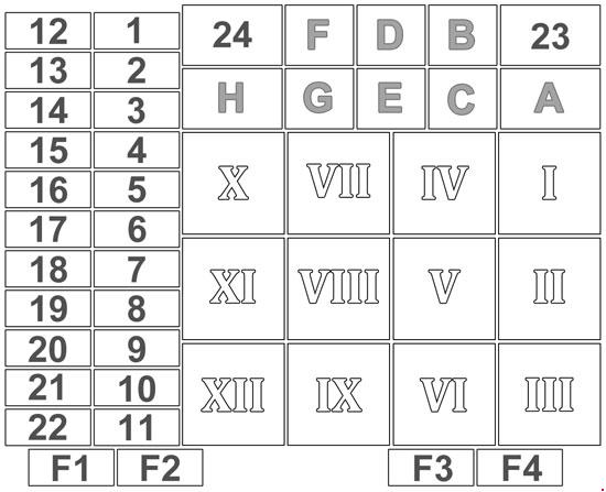
Central dashboard fuse panel: on left-hand-drive European vehicles the main assembly is under the driver’s dashboard to the left of the steering column. Switch off the ignition, withdraw the key, open the driver’s door and slide the seat back. Locate the protective panel beneath the instruments, unclip the plastic cover carefully and identify the numbered blade fuses and distinct lettered/Roman-numeral relay locations.
The main carrier also has F1-F2 spare holders and F3-F4 ABS fuses on equipped vans. Many converted minibuses, ambulances, campervans and vehicle body-builder installations have additional dedicated fuses outside this Ford assembly. Those auxiliary circuits do not automatically follow the positions 1-24 below.
Because original fuseboard covers and clips can be brittle after decades, do not prise them with force. If a replacement fuse fails again, diagnose the load and wiring rather than increasing its rating.
Ford Transit 1992-1995 – all 48 fuse and relay entries
This diagram shows the 24 main positions, F1-F4, eight lettered relays A-H and Roman-numbered relay sockets I-XII. All unused locations and optional equipment are recorded. Main beams are on 13/14 (10 A), dipped beams on 1/2 (10 A), cabin heating blower on 19, and the front wiper motor on 20 (15 A).
Technical qualification at position 19: the retained Polish reference and some published schematics specify 20 A for the heater blower, whereas another Transit 1986-2000 technical compilation specifies 28 A for 1992-1995. The table preserves the actual source value of 20 A rather than silently mixing the two specifications. Confirm the correctly rated fuse in your particular factory-equipped carrier.
| Position | Amperage [A] | Protected circuit / function |
|---|---|---|
| 1 | 10 | Right dipped-beam headlamp, separate from the left headlight |
| 2 | 10 | Left dipped-beam headlamp, separately fused |
| 3 | 10 | Right position and tail lamps, licence plate light, high roof marker lamps and selected cabin lights |
| 4 | 10 | Left position and tail lamps and number plate light |
| 5 | 20 | Heated rear-window supply and defogger relay on glazed vehicles |
| 6 | 20 | Headlamp washer pump and control circuit where equipped |
| 7 | 20 | Electrically heated front windscreen relay supply on equipped models |
| 8 | 3 | Fuel system ECU supply, primarily turbo diesel versions |
| 9 | 20 | Front cigarette lighter and factory 12 V accessory socket |
| 10 | 10 | Interior lighting, radio memory, clock and front windscreen washer pump |
| 11 | 20 | Horn and hazard warning flasher circuits |
| 12 | 10 | Headlamp washer control circuit and rear position lamps |
| 13 | 10 | Right high-beam headlamp and high-beam indicator on dashboard |
| 14 | 10 | Left high-beam headlamp |
| 15 | 10 | Optional heated seats, dashboard instrumentation lighting and mirror heating |
| 16 | 10 | Brake lamps, reverse lights, automatic gearbox lock switch, diesel water-in-fuel sensor and selected turbo diesel oxygen-sensor circuits |
| 17 | 10 | Left and right direction indicators |
| 18 | 3 | ABS antilock brake controller, on equipped vehicles |
| 19 | 20 | Cabin heater/ventilation blower: 20 A in the preserved table, but some technical sources specify a different rating; use the fitted cover/vehicle documentation |
| 20 | 15 | Front windscreen wiper motor and control stalk |
| 21 | 15 | Automatic transmission kickdown solenoid on equipped gearbox versions |
| 22 | 15 | Rear windscreen wiper where fitted |
| 23 | 3 | Main power relay control on turbo diesel versions |
| 24 | 20 | Reduced-intensity dipped headlights (dim-dip) on relevant market versions |
| F1 | – | F1: holder for spare replacement fuse, no active consumer |
| F2 | – | F2: second spare replacement fuse holder, no active consumer |
| F3 | 30 | F3: ABS main protection fuse, optional ABS system |
| F4 | 30 | F4: additional ABS main fuse on equipped vehicles |
| A | – | Relay A: reduced-intensity dipped headlight system (dim-dip) |
| B | – | Relay B: normal dipped-headlight power relay |
| C | – | Relay C: unused relay socket |
| D | – | Relay D: unused relay socket |
| E | – | Relay E: electrical power management relay |
| F | – | Relay F: main power supply relay |
| G | – | Relay G: accessory power feed relay |
| H | – | Relay H: heated rear-window relay |
| I | – | Relay I: unused relay socket |
| II | – | Relay II: unused relay socket |
| III | – | Relay III: unused relay socket |
| IV | – | Relay IV: electrically heated windscreen relay |
| V | – | Relay V: rear window wiper relay |
| VI | – | Relay VI: automatic gearbox kickdown solenoid relay |
| VII | – | Relay VII: direction-indicator flasher |
| VIII | – | Relay VIII: headlamp washer pump relay |
| IX | – | Relay IX: front windscreen wiper relay |
| X | – | Relay X: heater blower motor relay |
| XI | – | Relay XI: unused relay socket |
| XII | – | Relay XII: unused relay socket |
Differences between the early and revised Transit fuseboard
From around 1992 Ford changed both the physical arrangement and the circuit numbers. In the older system the cigarette lighter used 20 (25 A), while the newer arrangement uses 9 (20 A). Headlight washer protection, headlamp relays and front wiper circuits also moved. This is why a 1992 registration by itself is not enough to select a diagram.
The later 1995-onward electrical redesign introduced further differences, including the structure of the central junction box. If the cover has another numbering sequence, identify that version instead of fitting a fuse from this table.
Common Transit 1992-1995 electrical faults
Cigarette lighter or charger has no power: inspect fuse 9 (20 A), remove the charger and check for shorted contacts. Accessory sockets installed by a camper converter may use separate protection.
One headlight is out: dipped beam uses 1 (right) or 2 (left), while main beam uses 13 (right) and 14 (left), all 10 A. If both dipped beams are out, also inspect relay B and the headlight switch.
Front wipers or washers fail: 20 (15 A) protects front wiper motor and controls, and 10 (10 A) serves the screenwash pump. Relay IX is the wiper relay. Headlamp washer vehicles additionally use fuses 6/12 and relay VIII.
Front or rear windscreen heating fails: the optional front heated windscreen is associated with 7 (20 A) and relay IV. Rear defogger feed is 5 (20 A) with relay H. Not all cargo and minibus body styles have electrically heated rear glazing.
ABS warning stays on: 18 (3 A) is a low-current ABS control supply, while F3 and F4 (30 A each) are higher-current ABS fuses on equipped vehicles. If intact, inspect wheel speed sensors, connectors and controller fault memory.
Cabin blower not running: locate 19 and relay X, but confirm fuse 19’s original rating because published technical references conflict. A blower that runs at one speed only can have a failed resistor pack or fan-speed switch.
Rear wiper fails: inspect 22 (15 A) and relay V. Solid-rear-door vans without a rear wiper may have these positions unpopulated.
Engines, markets and optional circuits
Engine options included naturally aspirated 2.5 diesel, 2.5 turbo diesel and petrol units. The turbo diesel fuel ECU uses fuse 8 (3 A), and 23 (3 A) can power its associated main relay. The automatic gearbox’s kickdown solenoid uses 21 (15 A) and relay VI where equipped.
ABS, heated front and rear windscreens, headlamp washers, trailer warning flashers and rear wiper are not standard on all vans. Check the actual fitted fuseboard and build month, especially in vehicles registered close to 1992 or 1995, before replacing any electrical component.
Other Ford Transit fusebox guides
For the previous layout see Ford Transit (1986-1992). The subsequent Ford Transit (1995-2000) uses a further revised panel; much later Transit Mk6 (2000-2006) has a wholly different distribution system.
Technical references: Ford Transit 1992-1995 electrical equipment service tables, with cross-checking against published workshop technical data. The 20 A versus 28 A discrepancy for position 19 is explicitly disclosed; follow the installed vehicle’s manufacturer’s fuse rating.
Featured vehicle photograph: Kieran White, “1993 Ford Transit 100 D LWB (12725047635).jpg”, Wikimedia Commons, CC BY 2.0, unmodified. Source and licence information are retained in WordPress media metadata.