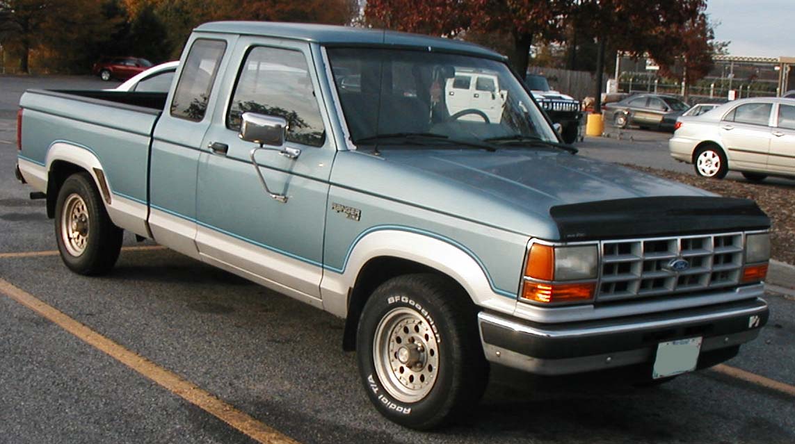
The Ford Ranger I (1983-1992) was the first generation of the compact North American Ford pickup, available in regular and SuperCab forms with 4×2 or 4×4 drivetrains. Its fuse arrangements changed during the production run, including different engine controllers, rear-wheel ABS, power windows and optional electric transfer-case shifting. Do not treat the entire 1983-1992 period as a single universal fusebox.
This guide retains all 60 original entries in four complete tables. The first two are an archived 1-18 passenger fuse list and a 1-10 engine power distribution list, with their original corresponding schematic images. The next two reproduce a different Ford 1989-1991 service reference: 17 numbered cabin positions, one repeated 6 for the 1989-1990 versus 1991 circuit-breaker rating, and ten engine distribution positions plus an optional 1991 under-bonnet lamp circuit. The same number can therefore represent different equipment on different physical panels.
Cigarette lighter and 12 V accessory socket: position 12, 20 A circuit breaker in the archived arrangement; position 3, 20 A circuit breaker in the separate 1989-1991 service reference. A resettable circuit breaker is not equivalent to an ordinary single-use blade fuse. Identify the installed carrier and electrical protection type before fitting any replacement.
Where are the first-generation Ford Ranger fuses?
Cabin fuse panel: with the ignition off, slide the driver’s seat back and locate the fuse access cover under the left end of the dashboard, to the left of the steering column, on the usual North American left-hand-drive vehicles. Pull the lower cover using its moulded hand recess rather than forcing the brittle trim. The inside of the original Ford panel cover shows the correct fuse and circuit-breaker map. Some covers also hold a small plastic puller and replacement fuses.
Engine power distribution box: on versions fitted with a separate high-current MAXI fuse carrier, open the bonnet after switching the ignition off and locate the protected junction box mounted on a fender-side bracket in the engine compartment, commonly near the driver’s-side inner fender in period Ford references. Release its lid and compare the printed numbers with the actual panel. The fact that one illustrated vehicle has a 1-10 engine power box does not establish that all Rangers from 1983 have the same carrier.
Special caution: many of these vehicles use resettable circuit breakers for wipers, power windows or the cigarette lighter. Do not substitute an ordinary blade fuse into a circuit-breaker socket. If a breaker trips repeatedly, inspect the load, wiring and the correct replacement part.
Archived interior fuseboard – all 21 source entries
The original source includes positions 1-18 but retains different amp variants at 14, 17 and 18, making 21 entries rather than 18. This archived reference includes position 12 (20 A) cigarette lighter circuit breaker, position 9 (30 A) cabin blower, position 15 (20 A) RABS and separate 4×4 electronics variants.
Applicability caution: no single precise model-year and engine combination has been independently verified for all three alternative positions in this archived list. Ranger electrical diagrams were revised repeatedly between 1983 and 1992. Match the actual cover and the diagram below rather than treating the archived table as a confirmed universal fuse allocation.
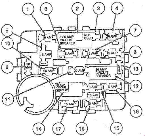
| Position | Amperage [A] | Protected circuit / function |
|---|---|---|
| 1 | 15 | Cabin dome and courtesy lamps and radio |
| 2 | 6 | 6 A self-resetting circuit breaker – front windscreen wiper and washer |
| 3 | – | Unused position in the archived fusebox |
| 4 | 15 | Hazard warning flashers, brake lights and cruise-control brake cut-off |
| 5 | 15 | Direction indicators, reverse lamps, rear defogger control and brake fluid level warning |
| 6 | 15 | Rear window wiper and washer motor on equipped bodies |
| 7 | 10 | Air-conditioning switches and compressor clutch coil |
| 8 | 20 | Vehicle horn |
| 9 | 30 | Cabin heater/ventilation blower motor |
| 10 | 15 | Side/parking lamps, number plate and bonnet lamp, lights-on warning |
| 11 | 15 | Cruise control and factory radio, plus optional 4WD electrical control |
| 12 | 20 | 20 A circuit breaker – cigar lighter, flash-to-pass and multifunction stalk control |
| 13 | 10 | Instrument cluster lighting and exterior side light control |
| 14 | 20 | Electric windows and electrically adjusted lumbar support, archived 20 A alternative |
| 14 | 30 | Same physical position 14, 30 A electric windows and lumbar support on selected 1991-1992 versions |
| 15 | 20 | Rear-wheel anti-lock braking system (RABS) electronic controller |
| 16 | 15 | Premium factory audio amplifier |
| 17 | 20 | Instrument warning lights and 4WD controls, first archived 20 A configuration |
| 17 | 15 | Same position 17, 15 A electric transfer-case control, low oil warning and dashboard signals, engine-specific alternative |
| 18 | 10 | Heated exhaust oxygen (HEGO) sensor, archived 10 A engine configuration |
| 18 | 15 | Same position 18, 15 A shift indicator, low fuel and seatbelt warning and carburettor status control |
Archived engine power distribution box – positions 1-10
In this older archived 1-10 reference, fuse 1 (60 A) is ignition, fuse 2 (40 A) is electric 4×4 shifting, fuse 3 (30 A) supplies the EEC controller relay, and fuses 4 (50 A) and 8 (60 A) are alternator power feeds. Other positions protect door locking, cabin fuse power, rear-window electrical equipment, headlights and fuel pump relay power.
This numbering is not the same as the Ford 1989-1991 distribution below; in particular a fuse 1 (60 A) is the ignition circuit here but the fuel-pump relay is number 1 (30 A) in the later table. Do not swap a high-current link from one panel into the other based on the model name.
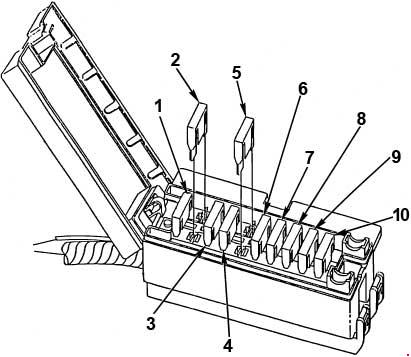
| Position | Amperage [A] | Protected circuit / function |
|---|---|---|
| 1 | 60 | Main ignition system high-current feed |
| 2 | 40 | Electric shift control for four-wheel drive transfer case |
| 3 | 30 | Main engine electronic control EEC relay supply |
| 4 | 50 | First alternator electrical power circuit |
| 5 | 40 | Rear window washer/wiper and defogger supply if equipped |
| 6 | 30 | Power-operated door locks |
| 7 | 40 | Main battery feed to passenger compartment fuse panel |
| 8 | 60 | Second alternator high-current feed |
| 9 | 40 | Headlight power distribution |
| 10 | 30 | Fuel pump relay feed |
Ford 1989-1991 service fuse and circuit-breaker allocation
The 1989-1991 Ford service reference has 17 cabin positions with 18 listed allocations because circuit breaker 6 changes from 20 A in 1989-1990 to 30 A in 1991 for power windows and electrically adjustable lumbar support. Positions 3, 6 and 17 are specifically described as circuit breakers, not conventional push-fit fuses.
Frequent checks include 3 (20 A) cigarette lighter, 12 (30 A) cabin blower, 17 (6 A) front wipers, 7 (20 A) rear-wheel ABS controller and 9 (20 A) electric 4×4 shift controller. Because the archived 1-18 image does not document this exact physical configuration, it is intentionally not reproduced here as a 1989-1991 factory drawing. Use the original fuse-cover legend or a matching Ford service diagram.
| Position | Amperage [A] | Protected circuit / function |
|---|---|---|
| 1 | 15 | Hazard flasher, brake lights and cruise-control cut-off switch |
| 2 | 20 | Vehicle horn |
| 3 | 20 | 20 A circuit breaker – cigarette lighter, headlamp flash-to-pass and multifunction switch |
| 4 | 10 | Instrument panel illumination and parking lamp switch |
| 5 | 15 | Premium factory radio amplifier |
| 6 | 20 | 20 A circuit breaker – powered windows and lumbar support, 1989-1990 variant |
| 6 | 30 | Same circuit breaker 6, 30 A powered windows and lumbar support, 1991 variant |
| 7 | 20 | Rear ABS (RABS) electronic control module |
| 8 | 10 | Exhaust oxygen sensor (HEGO) heater |
| 9 | 20 | Instrument warning lights and electric 4WD transfer-case shift controls |
| 10 | 15 | Cruise-control electronics, radio and optional electric 4WD |
| 11 | 15 | Exterior position/parking and registration plate lights |
| 12 | 30 | Heater and air-conditioning blower motor |
| 13 | 15 | Turn signals, reverse lights and heated rear window control |
| 14 | 15 | Interior dome and courtesy lamps |
| 15 | 15 | Rear window wiper and washer on equipped vehicles |
| 16 | 10 | Air-conditioning controls and compressor clutch |
| 17 | 6 | 6 A circuit breaker – front wiper and washer motor |
Ford 1989-1991 engine power distribution – eleven entries
The Ford service distribution list includes ten main high-current fuses plus an extra 1991-specific under-bonnet lamp feed at position 11 (15 A), which may not be visible in a standard 1-10 drawing. This separate chart puts the fuel pump relay at 1 (30 A), headlights at 2 (40 A), central fuse panel at 4 (40 A), the electric shift motor at 9 (40 A) and main ignition at 10 (60 A).
Some closely related Explorer or Bronco II diagrams show different optional circuits or another alternator field supply. They are not proof that every Ranger carried that same fuse; the table here preserves the exact 1989-1991 Ranger reference and its optional 1991 position.
| Position | Amperage [A] | Protected circuit / function |
|---|---|---|
| 1 | 30 | Fuel pump power relay feed |
| 2 | 40 | Headlights and front power distribution |
| 3 | 60 | Second high-current alternator supply |
| 4 | 40 | Main feed to cabin fusebox |
| 5 | 30 | Central door locking electric actuators |
| 6 | 40 | Rear window defogger and associated rear-glass equipment |
| 7 | 50 | First alternator high-current supply |
| 8 | 30 | Electronic engine control EEC main relay feed |
| 9 | 40 | Electric four-wheel-drive transfer-case shift motor |
| 10 | 60 | Main ignition electrical supply |
| 11 | 15 | Additional 1991-only 15 A engine compartment lamp circuit, not present in the basic 1-10 drawing |
1983-1992 engine, transmission and equipment differences
Depending on year and market the Ranger used 2.0 or 2.3-litre four-cylinder petrol engines, 2.8, 2.9 and 4.0 V6 petrol engines and less-common diesels. Carburettor-equipped early models and EEC fuel-injected later engines do not have identical ignition, lambda-sensor and fuel-pump control wiring. A 1992 model may also differ from the 1989-1991 service sample.
4×4 models can have an electric transfer-case shift motor, whereas a 4×2 Ranger lacks those loads; RABS rear-wheel anti-lock braking, cruise control, power windows, Premium audio and rear wipers/defoggers are also market/body dependent. These optional features explain why apparently unoccupied fuse locations can still appear in a broad reference chart.
Typical early Ranger electrical failures
Front 12 V cigarette lighter stops working: inspect the archived 12 (20 A breaker) or the 1989-1991 Ford service 3 (20 A breaker), depending on the installed panel. Remove any charger and check the socket for damaged contacts or loose metal before replacing the correctly specified breaker.
Wipers or washers are inoperative: the archived chart lists 2 (6 A breaker); the later service chart lists 17 (6 A breaker). If the correct breaker is intact, test the wiper linkage, motor, column switch and washer wiring.
Heater blower does not run: the archived layout uses 9 (30 A) while the Ford 1989-1991 table uses 12 (30 A). A blower that runs only at its highest setting often has a failed resistor pack, switch or motor connection.
4×4 transfer case will not shift: the archived engine box uses 2 (40 A); the Ford 1989-1991 service box uses 9 (40 A). Also test the transfer-case motor, shift switch, connector and grounding before replacing the actuator.
RABS warning remains lit: the archived cabin list uses 15 (20 A), while the Ford service list uses 7 (20 A). Diagnose the ABS controller, rear axle speed sensor and cable routing after verifying the correct power feed.
Starting or charging problem: verify the 12 V battery, starter solenoid, ground straps and the relevant ignition/alternator high-current fuses for the actual PDB layout. Never uprate a 30-60 A fuse to bypass an intermittent fault.
Related Ford Ranger fusebox generations
The redesigned Ford Ranger (1993-1997) has a different instrument panel and electrical distribution. Later Ford Ranger (1998-2000) and Ford Ranger (2001-2003) also require their own fuse and relay guides. North American Ranger electrical layouts cannot be copied into European Mazda-derived Ford Ranger models.
Technical reference: first-generation Ford Ranger fuse charts and 1989-1991 Ford “Fuses & Circuit Breakers” workshop service data, with diagrams compared against the early and later Ranger fuseboard examples documented by The Ranger Station. Original archived diagrams remain with their matching tables; the independent 1989-1991 fuse lists deliberately have no unverified physical drawing attached.