Ford Transit Mk7 TT9 (2006-2013) uses four main fuse and relay assemblies: the high-current fuse block below the driver’s seat, the engine compartment fuse box and two panels behind the passenger glove compartment. Additional protection may be fitted for trailers, diesel particulate filter systems, camper conversions or other commercial bodywork.
This guide preserves the separate allocations documented in the Ford CG3527pl July 2008 and CG3527pl July 2012 owner’s manuals, the latter covering vehicles from 26 September 2011 through 31 December 2013. Where a fuse number has more than one row, those are alternative configurations, not several fuses installed together.
Cigarette lighter: position 47 (20 A) in the standard relay box behind the glove compartment. The front auxiliary 12 V socket uses 45 (20 A), while the rear auxiliary outlet uses 49 (20 A). Always compare the handbook year with the actual fuse layout before replacement.
Where are the Transit Mk7 fuse boxes?
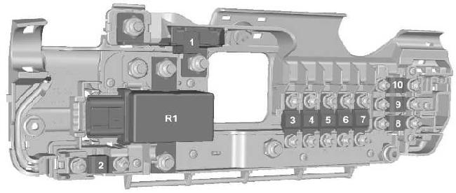
Below the driver’s seat: the high-current fuse block 1-10 and auxiliary battery relay R1 are installed in the seat base near the battery or batteries. With the ignition and electrical equipment off, move the seat as permitted by its adjustment, find the lower cover and release it. This provides access to bolted protection including the main 350 A link. These large fuses are not ordinary plug-in blade fuses; do not remove them without the correct service and battery isolation procedure.
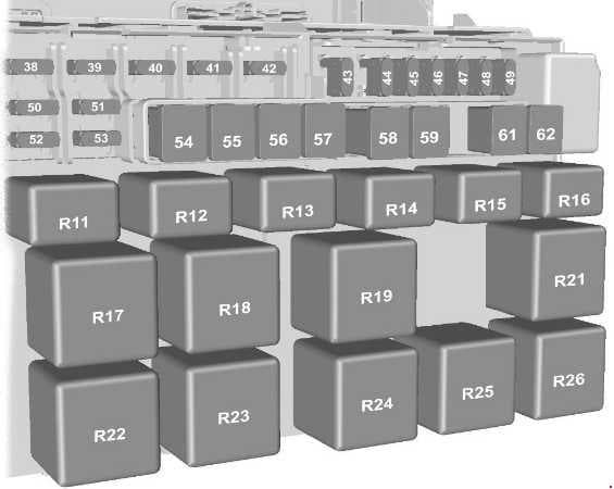
Behind the front passenger glovebox: two separate fuse carriers are fitted. Switch off the ignition and empty the glovebox. Open it, release the side stops and gently lower the box. The standard relay box has positions 38-62 and R11-R26; the passenger junction box has 63-82. Right-hand-drive models can have a different trim access route. Restore the box and both side stops before driving.
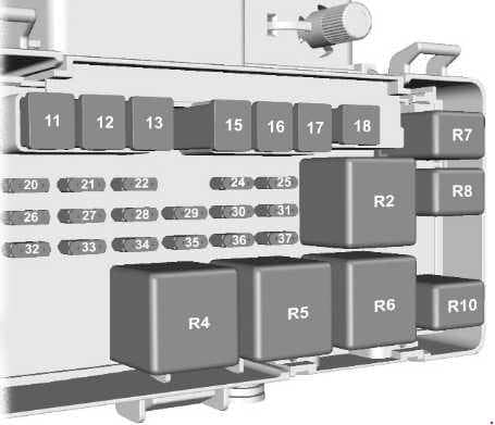
Under the bonnet: the engine fuse box has positions 11-37 and relays R2-R10. Open the bonnet and find the covered fuse carrier near the left side of the engine compartment, in the vehicle’s driving direction. Release the cover clips and check the physical numbering. Follow Ford’s safety procedure before touching bolted fuses or battery distribution connections.
Commercial conversions: vans with a caravan, refrigeration body, lift or extra accessory circuits can have additional fuses fitted by the converter. Their locations and numbering are independent of the standard Ford positions 1-84.
High-current fuses under the seat – 1-10 and R1
Position 1 (350 A) provides starter and alternator protection, with separate feeds for the cabin and engine box. Positions 4 and 6 (40 A each) supply the right and left heated windscreen sections. Positions 8, 9 and 10 (60 A each) are customer connection points for optional equipment. R1 controls the additional battery isolation circuit where a dual-battery system is fitted.
| Position | Amperage [A] | Protected circuit / function |
|---|---|---|
| 1 | 350 | Starter motor and alternator main high-current link |
| 2 | 60 | Passenger compartment fuse panel, starting-related feed; terminal 15 circuit on Start-Stop versions |
| 3 | 100 | Engine fuse box permanent power supply |
| 4 | 40 | Heated windscreen, right-hand side |
| 5 | 100 | Standard relay box supply, not interrupted by engine starting |
| 6 | 40 | Heated windscreen, left-hand side |
| 7 | 60 | Passenger fuse box feed, independent of starting |
| 8 | 60 | Customer connection point (CCP) for auxiliary equipment |
| 9 | 60 | Customer connection point (CCP) for auxiliary equipment |
| 10 | 60 | Customer connection point (CCP) for auxiliary equipment |
| R1 | – | Auxiliary battery isolation relay on dual-battery vehicles only |
Engine compartment fuse box – 11-37 and relays R2-R10
The engine box includes cooling fan 11 (60 A), starter control 17 (30 A), ABS/ESP 13 (40 A) plus 20 and 21, glow plugs 15 (60 A), fuel supply and A/C compressor protection. The table retains every spare position and all nine relays, plus petrol and diesel alternatives.
Model-year differences: position 22 is a 20 A PCM relay feed in the 2008 listing, but unused in the 2012 version. Position 25 similarly changes from 5 A to unoccupied. Assignments for 24, 27-32, 35 and 37 also vary. The entries remain separate so a 2008 vehicle is not accidentally fitted with a 2012 configuration. Start-Stop equipment can also alter position 18.
| Position | Amperage [A] | Protected circuit / function |
|---|---|---|
| 11 | 60 | Engine cooling fan |
| 12 | 30 | Trailer electrics module and socket permanent battery supply (KL30) |
| 13 | 40 | ABS/ESP hydraulic pump |
| 14 | – | Unused position in the specified layout |
| 15 | 60 | Diesel glow plugs |
| 16 | 60 | Ignition supply relay KL15 #3 |
| 17 | 30 | Starter control circuit |
| 18 | 40 | Start-Stop version: position described with 40 A in one source arrangement |
| 18 | – | Start-Stop version: unoccupied in alternative arrangement |
| 19 | – | Unused position |
| 20 | 10 | ABS, ESP, steering angle and yaw rate sensors, permanent supply (KL30) |
| 21 | 25 | ABS/ESP solenoid valves and control module |
| 22 | – | Unused according to the 2012 owner’s manual |
| 22 | 20 | PCM power relay – 2008 handbook; unoccupied in 2012 edition |
| 23 | – | Unused position |
| 24 | 5 | Fuel pump without fuel-fired heater – 2012 handbook |
| 24 | 20 | Diesel fuel-fired auxiliary heater – 2008 handbook |
| 24 | 20 | Petrol engine fuel pump – 2008 handbook |
| 24 | 20 | Fuel pump with fuel-fired heater – 2012 handbook |
| 25 | – | Unused according to the 2012 owner’s manual |
| 25 | 5 | Battery-powered relay coils – 2008 handbook; unoccupied in 2012 |
| 26 | 15 | Powertrain control module (PCM) |
| 27 | 5 | Fuel pump with fuel-fired heater |
| 27 | 7.5 | Glow plug monitoring – 2008 handbook alternative rating and assignment |
| 28 | 5 | T-MAF sensor – 2012 version |
| 28 | 5 | Diesel T-MAF sensor – 2008 handbook |
| 28 | 15 | Catalytic converter monitoring and HEGO oxygen sensor – petrol 2008 version |
| 29 | 5 | Auxiliary heater glow plug monitoring – 2012 handbook |
| 29 | 5 | Diesel fuel water sensor and relay coils – 2008 handbook |
| 30 | 7.5 | Fuel vapour purge valve – 2012 handbook |
| 30 | 10 | Fuel vapour purge valve and petrol injectors – 2008 handbook |
| 31 | 15 | VAP/UEGO pump system – 2012 handbook |
| 31 | 5 | Vehicle speed sensor – 2008 handbook |
| 32 | 20 | Injector glow plug / aftertreatment system – 2012 version |
| 32 | 20 | Petrol ignition coil module – 2008 handbook |
| 33 | 10 | Reversing lamps |
| 34 | 20 | Trailer power supply, ignition-switched KL15 |
| 35 | – | Unused according to the 2012 owner’s manual |
| 35 | 5 | Auxiliary heater ignition-switched supply KL15 – 2008 handbook; unoccupied in 2012 |
| 36 | 10 | Air-conditioning compressor clutch |
| 37 | – | Unused according to the 2012 owner’s manual |
| 37 | 5 | PCM relay coils and ignition signal – 2008 handbook; unoccupied in 2012 |
| R2 | – | Glow plug relay |
| R3 | – | Trailer ignition-switched power relay (KL15) |
| R4 | – | Starter motor relay |
| R5 | – | Ignition supply relay KL15 #4 |
| R6 | – | Ignition supply relay KL15 #3 |
| R7 | – | Fuel pump relay |
| R8 | – | Injector glow plug relay |
| R9 | – | Not specified in the source diagram: verify the fitted R9 relay, if present |
| R10 | – | Air-conditioning compressor clutch relay |
Standard relay box – fuses 38-62 and relays R11-R26
This box behind the glovebox supplies accessory outlets, headlamps, wipers, heated glass, cabin heaters and the tachograph. Fuse 47 (20 A) protects the cigarette lighter; auxiliary front and rear sockets use 45 and 49 (20 A each). Position 55 (40 A) protects the cabin blower, 58 (30 A) the front wipers and 59 (30 A) rear window and mirror heating.
Sixteen distinct relay positions R11-R26 follow the fuses, including R20 used for Start-Stop arrangements. Do not confuse these relays with the R2-R10 carrier in the engine compartment.
| Position | Amperage [A] | Protected circuit / function |
|---|---|---|
| 38 | 20 | Rear window wiper, if equipped |
| 39 | 10 | Front and rear air-conditioning controls |
| 40 | 5 | Unused position, shown as 5 A in the manual |
| 41 | 5 | Tachograph |
| 42 | 5 | Headlamp levelling and main lighting switch (KL15) |
| 43 | 20 | Heated front seats |
| 44 | 20 | Horn |
| 45 | 20 | Front auxiliary 12 V power socket |
| 46 | 10 | Heated door mirrors on category 1 alarm versions |
| 47 | 20 | Cigarette lighter and 12 V power outlet |
| 48 | 5 | Relay coils and electric exterior mirror adjustment |
| 49 | 20 | Rear auxiliary 12 V power socket |
| 50 | 10 | Left main-beam headlamp |
| 51 | 10 | Right main-beam headlamp |
| 52 | 10 | Left dipped-beam headlamp |
| 53 | 10 | Right dipped-beam headlamp |
| 54 | 30 | Main circuit for dipped/main beams, daytime running lights, tachograph and fuel-fired heater fan |
| 55 | 40 | Passenger compartment heater blower |
| 56 | 20 | Electric windows |
| 57 | 30 | Rear cabin heater blower motor |
| 58 | 30 | Front windscreen wiper motor |
| 59 | 30 | Heated rear door windows and electric exterior mirrors |
| 60 | – | Unused position in the described layout |
| 61 | 60 | Ignition power relay KL15 #1 |
| 62 | 60 | Ignition power relay KL15 #2 |
| R11 | – | Dipped-beam headlamp relay |
| R12 | – | Heated mirrors with category 1 alarm, or power socket without it |
| R13 | – | Main-beam headlamp relay |
| R14 | – | Horn relay |
| R15 | – | Daytime running light relay |
| R16 | – | Programmable fuel-fired heater relay |
| R17 | – | Heated rear windows and mirrors; left rear window on category 1 alarm versions |
| R18 | – | Right rear window heater on category 1 alarm versions |
| R19 | – | Ignition supply relay KL15 #2 |
| R20 | – | Cabin ignition supply relay KL15 for Start-Stop only |
| R21 | – | Ignition supply relay KL15 #1 |
| R22 | – | Right half heated windscreen relay |
| R23 | – | Front wiper speed selection relay |
| R24 | – | Rear window wiper relay |
| R25 | – | Front wiper on/off relay |
| R26 | – | Left half heated windscreen relay |
Passenger fuse box – positions 63-82
The second glovebox panel provides protection for washers, the instrument cluster, PATS immobiliser, brake lights, indicators, antitheft alarm, radio, number plate lighting and central locking. Position 63 (5 A) serves parking and rain sensors; 65 (15 A) the brake lamp switch and 72 (10 A) the OBD-II diagnostic circuit.
Ford’s 2006 English handbook describes position 67 as a wiper switch supply with a different rating; the 2008 and 2012 Polish editions identify 67 (15 A) as the windscreen washer pump circuit. Position 82 also has an alternative 2006 rating. These differences must not be applied across production years without checking the fitted vehicle.
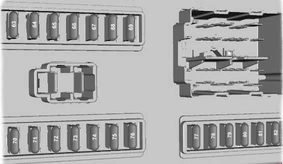
| Position | Amperage [A] | Protected circuit / function |
|---|---|---|
| 63 | 5 | Rear parking sensors and rain sensor |
| 64 | 2 | Accelerator pedal position sensor |
| 65 | 15 | Brake lamp switch |
| 66 | 5 | Instrument cluster, PATS immobiliser, tachograph and switch illumination |
| 67 | 15 | Windscreen washer pump – 2008 and 2012 handbooks |
| 67 | 10 | Windscreen wiper stalk switch – 2006 handbook variant; do not apply to 2008-2013 |
| 68 | 10 | SRS airbag and seat-belt pretensioner ECU |
| 69 | 20 | Exterior light switch (KL15) |
| 70 | 20 | Self-powered antitheft alarm siren |
| 71 | 5 | Exterior light switch permanent supply (KL30) |
| 72 | 10 | Battery saver control and OBD-II diagnostic socket (KL30) |
| 73 | 15 | Radio, navigation and telephone |
| 74 | 5 | Instrument cluster, fuel-fired heater timer, remote central locking and interior motion sensor (KL30) |
| 75 | 7.5 | Right side lamps |
| 76 | 7.5 | Left side lamps |
| 77 | 5 | Ignition switch and battery isolation relay coils |
| 78 | 15 | Central locking |
| 79 | 7.5 | Number plate lights and side marker lamps |
| 80 | 15 | Front fog lamps |
| 81 | 10 | Rear fog lamps |
| 82 | 3 | Audio system and instrument cluster ignition-switched feed |
| 82 | 2 | Audio system and gauges – 2006 handbook variant; later editions show 3 A |
Additional fuse locations 83 and 84
Neither fuse is part of the regular 63-82 row. 83 (10 A) protects a trailer electrical module located in the left footwell. 84 (7.5 A) protects diesel particulate filter glow-plug monitoring below the engine junction box on equipped vehicles. The 2008 documentation lists position 83, while the later edition additionally includes 84.
| Position | Amperage [A] | Protected circuit / function |
|---|---|---|
| 83 | 10 | Trailer electrics controller, located in the left-side footwell |
| 84 | 7.5 | Diesel particulate filter glow plug monitoring, below engine junction box on equipped vehicles |
Electrical variations between 2006, 2008 and 2011-2013
Earlier vans used Duratorq TDCi 2.2 and 2.4 diesels, with 3.2 diesel and 2.3 Duratec petrol versions in certain markets. Later engine and emissions revisions changed power feeds for the fuel pump, DPF system, engine ECU and auxiliary heating. Start-Stop also changed KL15 and battery-management circuits.
For example, 2008 position 24 (20 A) covers a diesel fuel-fired heater or petrol fuel pump, whereas the 2012 position 24 can be 5 A without a fuel-fired heater or 20 A with one. Position 28 also varies by engine type. Consult the manual for the VIN and build date, not the later 2014-on Transit Mk8 diagram.
Common Transit Mk7 electrical faults
Cigarette lighter or 12 V socket not working: inspect fuse 47 (20 A) behind the glovebox. For the extra front socket use 45 (20 A), and for the rear socket 49 (20 A). Conversions may have separate accessory fuse holders.
One dipped beam has failed: behind the glovebox, position 52 (10 A) supplies the left lamp and 53 (10 A) the right. Main-beam fuses are 50 and 51. If both lamps fail, check relay R11 and headlight connectors.
Wipers are unresponsive: inspect 58 (30 A) and relays R23/R25, then passenger fuse 67 for the washer circuit, subject to model year. A rear wiper, where fitted, uses 38 (20 A) and R24.
Cabin blower not running: the main supply is 55 (40 A). A blower operating only at full speed often indicates a failed speed resistor or controller, rather than a high-current fuse.
Starting or charging problems: check battery and earth connections. The main 350 A fuse below the driver’s seat is a high-current component and should be inspected or replaced by a qualified technician, not bypassed with a jumper cable.
Heated windscreen works on one side only: inspect fuses 4 and 6 (40 A each) and glovebox relays R22 and R26. One-sided failure can also indicate wiring or heated glass element damage.
Related Ford Transit models
The preceding generation is described in Ford Transit Mk6 (2000-2006). For a narrower early European wiring arrangement, see Ford Transit Mk7 (2006, European model). The successor has a separate wiring system described in Ford Transit Mk8 V363 (2014-2018). Transit Custom and Transit Connect are different vehicle families as well.
Manufacturer reference: Ford Transit CG3527pl 07/2008 and CG3527pl 07/2012 owner’s manuals, compared for different engine and electrical variants. For 2006 models and non-European imports, the applicable VIN-specific manual takes priority.
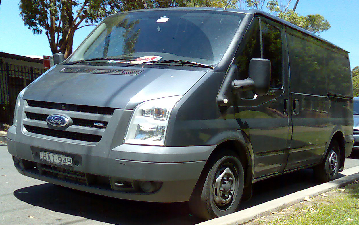
Featured vehicle photo: Ford Transit VM 2006-2008, photographed November 2008 in Gymea, Australia, by OSX, Wikimedia Commons, public domain.