
The Ford Tourneo Connect Mk1 (2002-2013) is the passenger version of the original Transit Connect, sold in Europe with 1.8-litre diesel and selected petrol powertrains. Electrical distribution is concentrated in the central dashboard fusebox and a separate engine-compartment fuse and relay carrier. During its production the dashboard installation changed considerably; the early panel has F30-F63 and the later version has F130-F182.
These layouts are not interchangeable. This guide retains all 156 original fuse and relay entries in three tables, including 43 entries in the early cabin box, 48 engine fuse/relay entries and 65 late cabin fuse/relay entries. The two cabin schematics and the engine schematic are preserved directly ahead of their matching tables. The later layout is supported by the Ford TourneoConnect/TransitConnect TC7 2012 owner manual, applicable to vehicles built from 24 May 2011 through 31 December 2013; earlier vans require their own correctly dated manual.
Cigarette lighter / front 12 V socket: early panel F44 (15 A) or late panel F143 (20 A). Later vans can also have F169 (20 A) for a second outlet and F174 (20 A) for a rear outlet or specialist conversion equipment. Identify the installed panel before using any of these numbers.
Where are the Ford Tourneo Connect Mk1 fuse boxes?
Dashboard fusebox: park, switch off ignition and electrical equipment, then move the front seat back. On a left-hand-drive TC7, Ford locates the main central fuse panel behind the lower dashboard trim to the left of the steering column. Release the cover without forcing the plastic clips and compare the physical fuse numbers with the early or later diagram. On right-hand-drive versions, the owner handbook shows a separate access arrangement; it may be necessary to release both sides of the glovebox and pivot it down. Follow the correct dashboard trim diagram, not an assumed mirror-image position.
Under the bonnet: open the bonnet after the engine has cooled and locate the protective electrical distribution box toward the rear/side of the engine compartment, adjacent to or behind the air-filter housing on many versions. Release the side catch and cover hinge to lift the lid without tugging on the wiring. Ford’s TC7 manual notes that the fuse puller is stored in this engine box. Close both lid hinges and catches fully after work to prevent water entering the panel.
Some under-bonnet large MAXI fuses require service by a trained technician, especially numbers 1-9 in the auxiliary box. Check the fuse rating printed on the cover and do not replace a bolted high-current link as if it were a small blade fuse.
How to tell early and late electrical configurations apart
Older Tourneo Connect Mk1 vehicles commonly have F30-F63 and relay positions R1-R9 in the dashboard carrier. Later first-generation vans use fuse numbers F130-F182 and relay references R117-R128. The electrical redesign occurred during production and is not determined solely by the vehicle’s first registration year.
The Ford owner handbook covering builds from May 2011 to December 2013 explicitly documents the late numbering and separate engine positions 1-29 plus 64 and 65. A facelifted 2006-2010 model may still have a distinct variation; always compare the fitted panel and chassis build date.
Early dashboard fusebox – F30-F63 and relays R1-R9
The original diagram depicts 34 numbered fuse positions followed by nine relays. Several positions were deliberately unused in this reference and are retained. Key circuits include F42 (15 A) brake lights, F43 (20 A) windscreen wipers, F44 (15 A) cigarette lighter, F49 (25 A) heated rear window and F61/F63 for the central locking and anti-theft system.
Relay R1 is the starter relay, R4 the front wiper relay, R7 the battery saver and R9 the heated rear-window relay. R5 and R6 are shown as unoccupied. This table must not be used on a later panel with F143 or F169.
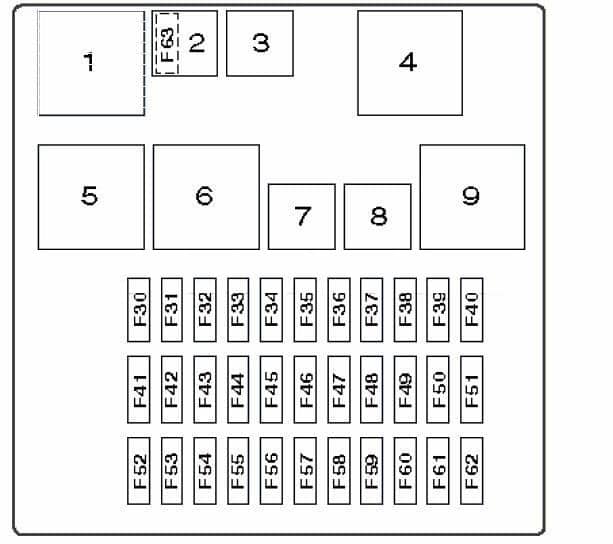
| Position | Amperage [A] | Protected circuit / function |
|---|---|---|
| 30 | 10 | Main light switch supply |
| 31 | 15 | Factory radio and audio equipment |
| 32 | – | Unoccupied fuse position in the early configuration |
| 33 | 7.5 | Battery-saver relay and interior courtesy lighting |
| 34 | 7.5 | Main ignition relay and optional fuel-fired heater controller |
| 35 | – | Unoccupied early fuse position |
| 36 | 7.5 | SRS airbag control module |
| 37 | 7.5 | Exterior light and turn signal stalk switches |
| 38 | 7.5 | Supplementary SRS electronics supply |
| 39 | – | Unoccupied early fuse position |
| 40 | 7.5 | Instrument cluster and factory radio |
| 41 | – | Unoccupied early fuse position |
| 42 | 15 | Brake light circuits |
| 43 | 20 | Front and rear windscreen wiper control |
| 44 | 15 | Front cigarette lighter and 12 V outlet |
| 45 | – | Unoccupied early fuse position |
| 46 | 15 | Factory trailer electrical socket |
| 47 | 5 | Electrically adjustable door mirror control switch |
| 48 | 7.5 | Instrument cluster, engine immobiliser, theft alarm and parking aid, as equipped |
| 49 | 25 | Heated rear window defogger |
| 50 | 7.5 | Electrically adjustable door mirrors |
| 51 | – | Unoccupied early fuse position |
| 52 | – | Unoccupied early fuse position |
| 53 | 10 | Reversing lamps and heated windscreen washer nozzles |
| 54 | – | Unoccupied early fuse position |
| 55 | – | Unoccupied early fuse position |
| 56 | 20 | Front windscreen wiper motor and relay power |
| 57 | 7.5 | Right-hand position/parking and tail lights and trailer lighting |
| 58 | 7.5 | Left-hand position/parking and tail lights |
| 59 | 7.5 | Optional fuel-fired auxiliary heater |
| 60 | – | Unoccupied early fuse position |
| 61 | 15 | Door central locking and factory alarm controller |
| 62 | 7.5 | Licence plate illumination |
| 63 | 20 | Central locking and vehicle anti-theft control |
| R1 | – | R1 – starter motor relay |
| R2 | – | R2 – rear window wiper relay |
| R3 | – | R3 – interior courtesy lamp relay |
| R4 | – | R4 – front windscreen wiper relay |
| R5 | – | R5 – unoccupied relay socket |
| R6 | – | R6 – unoccupied relay socket |
| R7 | – | R7 – battery saver relay |
| R8 | – | R8 – main ignition circuit relay |
| R9 | – | R9 – heated rear window relay |
Engine compartment fusebox – F1-F29, F64-F65 and R1-R16
The engine carrier protects cooling fans, ignition, engine management PCM, diesel glow plugs, heated windscreen, ABS, headlights, blower and optional fuel-fired heating. The source contains two alternatives at position 5: 5 (40 A) for a single cooling fan or 5A (50 A) for a dual cooling-fan arrangement. These are configuration alternatives, not instructions to fit both.
F4 (60 A) is the main heated-windscreen supply, F6 (60 A) protects diesel glow plugs, F12 (20 A) protects starter solenoid power, F13 (30 A) the ABS pump, F64 (30 A) the cabin blower and F65 (7.5 A) heated windscreen control. All sixteen original R1-R16 relay locations are retained, including the unused R15.
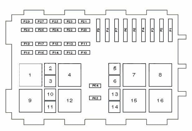
| Position | Amperage [A] | Protected circuit / function |
|---|---|---|
| 1 | 40 | Main supply to central passenger compartment fusebox |
| 2 | 30 | Second high-current protection for dual radiator cooling fan |
| 3 | 30 | Second main feed to central passenger compartment junction box |
| 4 | 60 | Electrically heated front windscreen main high-current supply |
| 5 | 40 | Single radiator cooling fan main fuse |
| 5A | 50 | 5A – alternative primary main fuse for twin cooling fan assembly, not a second fuse 5 to fit |
| 6 | 60 | Diesel glow plug electrical supply |
| 7 | 40 | Third main feed to passenger compartment junction box |
| 8 | 20 | Ignition switch power supply |
| 9 | 20 | Engine management PCM supply |
| 10 | 10 | Battery voltage monitor and diagnostic data link connector |
| 11 | 20 | Fuel-fired auxiliary heater controller |
| 12 | 20 | Starter motor solenoid circuit |
| 13 | 30 | ABS brake hydraulic pump |
| 14 | 10 | PCV and fuel volume control valve on equipped engines |
| 15 | 10 | Left high-beam headlamp |
| 16 | 10 | Left dipped-beam headlamp |
| 17 | 10 | Right dipped-beam headlamp |
| 18 | 10 | Engine PCM power and vehicle speed sensor |
| 19 | 20 | Daytime running lights operating as position lamps |
| 20 | 1 | Low-current PCM electronic control feed |
| 21 | 20 | Fuel vaporiser or auxiliary evaporator pump where fitted |
| 22 | 20 | Daytime running lights operating with dipped-beam lamps |
| 23 | 20 | ABS hydraulic control valves |
| 24 | 10 | Diesel glow plug monitoring control |
| 25 | 10 | Right high-beam headlamp |
| 26 | 10 | Air-conditioning compressor clutch solenoid |
| 27 | 10 | Engine sensors, actuators and control relay coils |
| 28 | 20 | Front fog lamps |
| 29 | 20 | Dipped-beam headlight relay supply |
| 64 | 30 | Heater/ventilation blower motor main feed (F64) |
| 65 | 7.5 | Electrically heated windscreen control supply (F65) |
| R1 | – | R1 – cooling fan relay, first stage |
| R2 | – | R2 – electronic throttle control relay if fitted |
| R3 | – | R3 – daytime running lamp relay |
| R4 | – | R4 – diesel glow plug relay |
| R5 | – | R5 – high-beam headlamp relay |
| R6 | – | R6 – dipped-beam headlamp relay |
| R7 | – | R7 – heated front windscreen relay |
| R8 | – | R8 – ignition main power relay |
| R9 | – | R9 – second radiator cooling fan relay |
| R10 | – | R10 – fuel-fired heater relay, stage 1 |
| R11 | – | R11 – vehicle horn relay |
| R12 | – | R12 – fuel-fired heater relay, stage 2 |
| R13 | – | R13 – fuel pump relay |
| R14 | – | R14 – engine management control relay |
| R15 | – | R15 – unoccupied relay socket |
| R16 | – | R16 – supplementary main ignition relay |
Later dashboard fusebox – F130-F182 and R117-R128
The later cabin box has 53 numbered fuse positions plus twelve relay references R117-R128. Its modern GEM body module distributes lighting, central locking, wipers, instrument cluster and accessory control. The complete table includes unused sockets without removing them or assigning invented protected circuits.
Ford specifies F143 (20 A) for the front cigar lighter and power point, F169 (20 A) for a second outlet and F174 (20 A) for a rear outlet and certain commercial body equipment. Other useful positions are F166 (25 A) for front electric windows, F163 (20 A) for door locking, F178 (25 A) for rear window heating and F180 (20 A) for front/rear wipers. The 2012 Ford TC7 handbook confirms that F173 is unused in this version.
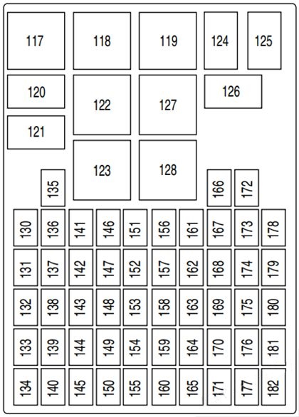
| Position | Amperage [A] | Protected circuit / function |
|---|---|---|
| 130 | 15 | GEM-controlled headlamp flash-to-pass supply |
| 131 | 5 | Electric exterior door mirrors |
| 132 | 10 | Light switch terminal 30 and GEM battery-fed exterior lighting |
| 133 | – | Not used in the later fusebox |
| 134 | – | Not used in the later fusebox |
| 135 | 10 | Light switch and daytime running lights |
| 136 | 15 | Vehicle horn |
| 137 | 7.5 | Factory radio and instrument cluster |
| 138 | – | Not used in the later fusebox |
| 139 | – | Not used in the later fusebox |
| 140 | – | Not used in the later fusebox |
| 141 | 10 | Reversing lamps and heated windscreen washer nozzles |
| 142 | 15 | Brake lights |
| 143 | 20 | Front cigarette lighter and front 12 V accessory outlet |
| 144 | – | Not used in the later fusebox |
| 145 | – | Not used in the later fusebox |
| 146 | 20 | Front windscreen wiper motor |
| 147 | 10 | Heated front seats where installed |
| 148 | 7.5 | GEM battery supply, recirculation and instrument cluster electronics |
| 149 | – | Not used in the later fusebox |
| 150 | – | Not used in the later fusebox |
| 151 | 15 | Radio memory and main power, Bluetooth/voice control |
| 152 | 7.5 | Air conditioning and parking assistance |
| 153 | 7.5 | Interior courtesy lamps and battery-saving function |
| 154 | – | Not used in the later fusebox |
| 155 | – | Not used in the later fusebox |
| 156 | 7.5 | Right position/parking lamps |
| 157 | 7.5 | Licence plate lamp |
| 158 | 7.5 | Light switch and rain sensor |
| 159 | – | Not used in the later fusebox |
| 160 | – | Not used in the later fusebox |
| 161 | 7.5 | ABS, stability control and steering angle sensor |
| 162 | 7.5 | SRS airbag controller and passenger airbag deactivation warning lamp |
| 163 | 20 | GEM battery feed to central door locking |
| 164 | – | Not used in the later fusebox |
| 165 | – | Not used in the later fusebox |
| 166 | 25 | Front power window lift motors |
| 167 | 7.5 | Heated side mirrors and rear screen |
| 168 | 10 | Daytime running lamps, parking lamps and licence plate illumination |
| 169 | 20 | Second 12 V accessory power socket |
| 170 | – | Not used in the later fusebox |
| 171 | – | Not used in the later fusebox |
| 172 | – | Not used in the later fusebox |
| 173 | – | Not used in the later fusebox |
| 174 | 20 | Rear power socket and auxiliary equipment used on certain converted vehicles |
| 175 | 7.5 | Left position/parking lamps |
| 176 | – | Not used in the later fusebox |
| 177 | – | Not used in the later fusebox |
| 178 | 25 | Heated rear window defogger |
| 179 | 7.5 | Instrument cluster, PATS immobiliser and accelerator pedal sensor |
| 180 | 20 | Front and rear windscreen wipers |
| 181 | – | Not used in the later fusebox |
| 182 | – | Not used in the later fusebox |
| R117 | – | R117 – unused relay location |
| R118 | – | R118 – unused relay location |
| R119 | – | R119 – unused relay location |
| R120 | – | R120 – dipped-beam headlamp interrupt relay |
| R121 | – | R121 – front fog lamp relay |
| R122 | – | R122 – heated rear window relay |
| R123 | – | R123 – heater/ventilation blower relay |
| R124 | – | R124 – cabin courtesy light relay |
| R125 | – | R125 – front windscreen wiper relay |
| R126 | – | R126 – rear door unlocking relay |
| R127 | – | R127 – ignition load reduction relay |
| R128 | – | R128 – battery-saver relay on specialist conversion versions |
2002-2013 production, diesel and optional equipment differences
Tourneo Connect’s 1.8 TDDi/TDCi diesel versions have glow-plug, PCM and optional fuel-fired heater circuits that are not present in the same form on a petrol version. Single or dual radiator fans, heated front screen, heated rear window, passenger versus utility body equipment, towbar and aftermarket converters also alter which cavities are populated.
The first generation was replaced by a substantially redesigned second-generation Tourneo Connect in 2013. Do not use the later model’s battery, interior and cargo fusebox allocation on a first-generation TC7. Ford’s factory fuse label on the back of the relevant trim shows the fuse number, current rating and function symbol for that particular vehicle.
Tourneo Connect electrical troubleshooting
Cigarette lighter does not work: check early cabin F44 (15 A) or late cabin F143 (20 A). A dead secondary socket in a late van may instead use F169 (20 A); the rear socket can use F174 (20 A). Remove chargers and check for bent contacts or loose metal objects before replacing the fuse.
Heater blower is silent: check engine F64 (30 A) and on the later model relay R123. If the fan operates only at maximum speed, investigate the resistor pack or blower controller rather than assuming a blown fuse.
Heated windscreen fails: engine F4 (60 A) supplies the system and F65 (7.5 A) is a separate control circuit. Damage to one glass-heating section can leave part of the screen cold even if the common supply is intact.
Central locking and electric windows fail: a late model uses F163 (20 A) for central locking and F166 (25 A) for front window power. In an older panel the alarm and locking electronics involve F61 and F63. Inspect door-pillar wiring and GEM connectors if a fuse is intact.
Wipers do not work: an early box lists F43 (20 A) for front/rear wipers, with further supply at F56. On the later system check F180 (20 A) and front wiper relay R125. Water entry at a relay box and worn wiper linkages can produce similar symptoms.
Engine fails to start: inspect battery voltage, engine F8/F9/F12, the relevant ignition/engine control relays and immobiliser fault codes. On diesel vans glow plug protection alone cannot diagnose starter failure.
Related Ford fusebox guides
The Ford Focus Mk1 (1998-2005) shares some C170-era Ford underpinnings, but its junction boxes use different fuse numbering. The Ford Focus Mk2 (2004-2011) uses a newer passenger-car electrical system and likewise cannot be substituted.
Primary manufacturer source: Ford TourneoConnect/TransitConnect TC7 Owner’s Handbook, July 2012 issue, “Fuses – Fuse Specification Chart”, printed pages 98-103, covering vehicles built 24 May 2011 to 31 December 2013. Early F30-F63 assignments are retained from the original year-specific technical reference and must be matched to the fitted fuseboard.