
The Ford Galaxy Mk1 (WGR, 1995-2006) is the first-generation European MPV related to the Volkswagen Sharan I and SEAT Alhambra I. Its electrical system changed during the production run, most visibly around the 2000 facelift. This guide therefore keeps two distinct dashboard fusebox layouts, type 1 and type 2, instead of combining their numbers or using a newer Galaxy Mk2 diagram.
The complete reference includes all 159 original fuse and relay entries in seven tables. These cover the early main panel, extra dashboard relays, early engine carrier, later main panel, under-seat protection, secondary relay level and third relay/high-current carrier. Unused positions, alternate engine ratings and unnamed high-current fuse slots remain visible. All six matching original schematics are placed immediately before their associated tables. The under-seat three-position carrier has no corresponding graphic in the source and is not falsely shown with an unrelated image.
Cigarette lighter / front 12 V socket: type 1 dashboard fuse 22 (10 A) in the archived early listing, or type 2 fuse 7 (20/25 A) according to equipment and production variant. The 2004 Ford Galaxy factory handbook specifies type 2 fuse 7 at 25 A for the alternator/regulator and cigarette lighter supply. Do not transfer that amperage automatically to an earlier panel.
Ford Galaxy WGR fusebox locations and access
Main cabin panel: park, switch the ignition off and open the driver’s door on a left-hand-drive Galaxy. Move the seat back, locate the lower dashboard cover beneath the steering column, release the service catch and lower the flap. The numbered fuses are behind this cover. On some configurations the upper part carries further relays and an additional second/third level behind the main board. Compare the physical panel’s numbering with type 1 and type 2 drawings before fitting a fuse; do not pull the wiring harness to reach rear-mounted relays.
Engine compartment: stop the engine and let the exhaust and coolant components cool. Open the bonnet and locate the protected distribution block near the battery and the main engine-compartment wiring. Separate cooling-fan and auxiliary heater relays may be adjacent or in an extra carrier. Remove the fuse cover using its latches and compare the diagram to the installed module. High-current glass heating, blower, glow-plug and fan links require appropriate battery isolation.
Under-seat protection: on some versions, a separate fuse/relay group lies beneath the front passenger seat for the luggage-area 12 V sockets and auxiliary battery. Slide the seat back or forward as needed, inspect the seat base, and unclip the protective cover without pinching airbag/seat wiring. Not every Galaxy has a second battery or an under-seat socket carrier.
Dashboard fusebox type 1 – 56 source entries
The earlier layout has 41 fuse allocations, including alternate values at fuse 15 for different engine/immobiliser circuits and at fuse 25 for glow-plug versus ECU control, followed by 15 relay positions R1-R15. It protects exterior lights, engine systems, windscreen heating, ABS, wipers, powered windows, trailer supply and cabin comfort equipment.
In the older reference, 22 (10 A) is the cigarette lighter. 27 (50 A) supplies the heated front screen and 28/29 (30 A) are ABS supply circuits. A later Galaxy built with the type 2 panel uses different numbers and must not be diagnosed with this first table.

| Position | Amperage [A] | Protected circuit / function |
|---|---|---|
| 1 | 10 | Left dipped-beam headlight, left headlamp height adjuster and instrument cluster |
| 2 | 10 | Right dipped-beam headlight, right headlamp levelling and instrument cluster |
| 3 | 3 | Number plate lighting and position lamps |
| 4 | 20 | Rear windscreen wiper motor and auxiliary rear heat exchanger |
| 5 | 10 | Front wiper motor and heated washer nozzles |
| 6 | 20 | Cabin heater blower and air conditioning control |
| 7 | 5 | Right tail lamp, right side position lamp and warning buzzer |
| 8 | 5 | Left tail lamp, side marker light and exterior light warning buzzer |
| 9 | 20 | Heated rear window defogger |
| 10 | 15 | Main light switch, front and rear fog lamps |
| 11 | 10 | Left high-beam headlamp and main-beam warning lamp |
| 12 | 10 | Right high-beam headlamp |
| 13 | 10 | Horn |
| 14 | 15 | Reversing lamps, automatic gearbox and cabin lamps |
| 15 | 10 | First engine immobiliser or ECU and crankcase heater circuit, 10 A alternative |
| 15 | 3 | Second engine immobiliser / ECU, EGR (AGR) and evaporative fuel valve (VMV), 3 A alternative for fuse 15 |
| 16 | 3 | Digital clock, front interior lamp and instrument panel |
| 17 | 10 | Direction indicators |
| 18 | 10 | Fuel inertia cut-off, engine ECU or fuel pump, HEGO oxygen sensor |
| 19 | 30 | Electric cooling or heater blower fan |
| 20 | 10 | Brake pedal light switch, brake lamps and trailer connection |
| 21 | 10 | Front/rear interior lights, clock, rear-view mirror, luggage lamp, radio and cluster |
| 22 | 10 | Front cigarette lighter and 12 V accessory socket |
| 23 | 7.5 | Engine cooling fan and air-conditioning control |
| 24 | 30 | Windscreen wiper motor high-current feed |
| 25 | 60 | Diesel glow-plug preheating system, 60 A alternative for fuse 25 |
| 25 | 3 | Second fuse 25 variant – engine electronic controller, 3 A |
| 26 | 5 | Heated exhaust oxygen HEGO sensor |
| 27 | 50 | Electrically heated front windscreen |
| 28 | 30 | ABS hydraulic pump module |
| 29 | 30 | ABS valves |
| 30 | 10 | Central door locking |
| 31 | 10 | Factory anti-theft alarm horn |
| 32 | 10 | Factory anti-theft hazard flasher circuit |
| 33 | 30 | Supplemental cabin blower heating |
| 34 | 25 | Rear heater/air-conditioning fan |
| 35 | 20 | Permanent battery supply for factory towing equipment |
| 36 | 10 | Telephone system |
| 37 | 30 | Electric window motors and controls |
| 38 | 20 | Electrically adjustable front seats |
| 39 | 25 | Front heater and air-conditioning blower system |
| R1 | – | R1 – auxiliary heater relay |
| R2 | – | R2 – rear windscreen wiper relay |
| R3 | – | R3 – main power supply relay |
| R4 | – | R4 – ignition load-shedding relay |
| R5 | – | R5 – unassigned relay location |
| R6 | – | R6 – turn-signal/hazard warning relay |
| R7 | – | R7 – headlamp washer relay |
| R8 | – | R8 – front screen wiper/washer relay |
| R9 | – | R9 – warning buzzer relay |
| R10 | – | R10 – rear fog lamp jumper connection, not a standard load relay |
| R11 | – | R11 – horn relay |
| R12 | – | R12 – petrol fuel-pump relay or diesel glow-plug control relay, engine-dependent |
| R13 | – | R13 – vehicle lighting relay |
| R14 | – | R14 – heated rear window relay |
| R15 | – | R15 – wiper load reduction relay |
Additional dashboard relay carrier – positions 18-26
Nine additional positions serve optional auxiliary heating, Scandinavian daytime running lamps, powered rear quarter windows, heated windscreen, Servotronic steering, electric windows and timed load-shedding warning electronics. These are relay references, not 18-26 A fuses. Their ratings correctly remain blank in this table.
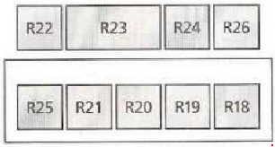
| Position | Amperage [A] | Protected circuit / function |
|---|---|---|
| 18 | – | Supplementary parking heater relay |
| 19 | – | Daytime running lamps relay |
| 20 | – | Freewheel clutch lock relay |
| 21 | – | Rear quarter/vent window electrical control relay |
| 22 | – | Heated front windscreen relay |
| 23 | – | Servotronic steering for 4WD-equipped models |
| 24 | – | Electric window lift relay |
| 25 | – | Load shedding/cut-off relay |
| 26 | – | Timed warning buzzer switching relay |
Type 1 auxiliary engine fuse and relay carrier
This smaller module contains 57 (30 A) for the second blower, 58 (40 A) for radiator cooling and 59 (30/40 A) for alternative fan configurations. Relay positions 50-56 cover fan speed stages, throttle cut-off, automatic transmission and supplementary air equipment. Check the exact engine and air-conditioning configuration, as 2.0, 2.3, 2.8 V6 and 1.9 TDI models use different cooling control approaches.
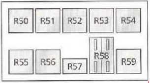
| Position | Amperage [A] | Protected circuit / function |
|---|---|---|
| 57 | 30 | Engine carrier fuse 57 – secondary fan or auxiliary blower |
| 58 | 40 | Engine carrier fuse 58 – cooling fan motor |
| 59 | 30 / 40 | Engine carrier fuse 59 – radiator cooling fan, rated 30 or 40 A according to version |
| 50 | – | Relay 50 – third cooling fan speed |
| 51 | – | Relay 51 – full-throttle cut-off / throttle deactivation |
| 52 | – | Relay 52 – second cooling fan speed |
| 53 | – | Relay 53 – time-delay relay |
| 54 | – | Relay 54 – first cooling fan speed or water-pump protective diodes |
| 55 | – | Relay 55 – automatic transmission control |
| 56 | – | Relay 56 – secondary air blower |
Later central dashboard fusebox type 2 – 48 entries
The later reference includes fuses 1-34 with some engine-specific variants, plus the secondary strip 51-62. It covers heated seats, electric windows, braking systems, engine control, air conditioning, cabin fans, additional heating, lighting, front washer/wiper systems and the cigarette lighter.
For the 2004 official Ford handbook, fuse 7 is 25 A for the alternator regulator and cigarette lighter. Earlier or differing source tables sometimes list 20 A; match the actual fuseboard label. The lower list also includes 14 at 10/20 A, 17 at 10/30 A, 21 at 25/30 A and 22 at 30/25 A for various petrol/diesel and HVAC configurations. Those alternatives are not selectable upgrades.
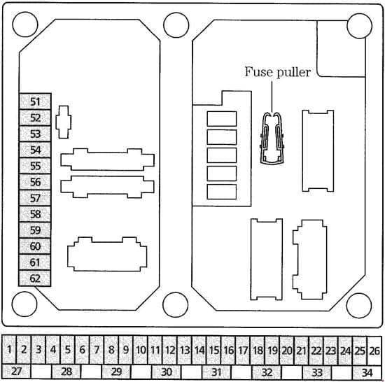
| Position | Amperage [A] | Protected circuit / function |
|---|---|---|
| 1 | 20 | Heated front seats |
| 2 | 10 | Power windows, powered/heated exterior mirrors and electrically operated rear vent windows |
| 3 | 5 | Digital dock, glovebox light, sunroof, parking aid, outside-temperature switch, ABS, climate, cruise control, navigation and central junction electronics |
| 4 | 10 | Engine management, immobiliser and reverse lamp control |
| 5 | 15 | Reversing lamps, automatic transmission and 4WD control |
| 6 | 10 | Vehicle horn |
| 7 | 25 / 20 | Front cigarette lighter and 12 V power outlet – 25 A or 20 A by production configuration |
| 8 | 30 | Auxiliary heater, auxiliary battery and trailer connector |
| 9 | 30 | ABS supply circuit 1 |
| 10 | 30 | ABS supply circuit 2 |
| 11 | 20 | Headlamp washer pump |
| 12 | 15 | Clock, central locking, rear wiper and powered roof |
| 13 | 3 | Engine ECU and fuel shut-off relay |
| 14 | 10 | Diesel fuel delivery control, first 10 A alternative for position 14 |
| 14 | 20 | Petrol fuel pump / ignition relay, 20 A alternative at position 14 |
| 15 | 30 | Cooling fan after-run feed for 2.8 V6 and diesel variants |
| 16 | 30 | First cooling fan speed thermostat |
| 17 | 10 | Automatic transmission supply, 10 A alternative for position 17 |
| 17 | 30 | Diesel glow plugs (66 kW TDI), second 30 A alternative for position 17 |
| 18 | 5 | Second cooling fan thermostat, HVAC, dashboard and fan after-run |
| 19 | 5 | Central locking, telephone, instrument panel, diagnostics, radio, air conditioning and parking sensors |
| 20 | 10 | Brake/stop lamps |
| 21 | 25 / 30 | Air conditioning supply, 25 or 30 A depending on vehicle |
| 22 | 30 / 25 | Second air-conditioning circuit, 30 or 25 A depending on version |
| 23 | 10 | Factory radio and CD changer |
| 24 | 25 | Diesel booster heater |
| 25 | 3 | Radio, telephone, belt warning and central junction box |
| 26 | 30 | Starter motor, automatic gearbox and ignition |
| 27 | 25 | Cooling fan after-run, HVAC blower, heated windscreen and auxiliary heater |
| 28 | 10 | V6 coolant pump, thermal switches, ABS and cooling fan controls |
| 29 | 5 | Front wiper/washer, heated jets, ventilation relay, climate, central panel and front/rear glass heating |
| 30 | 3 | Licence plate lights |
| 31 | 15 | Front fog lamps |
| 32 | 3 | Ignition relay, fuel pump, engine ECU, diesel glow-plug control |
| 33 | 25 | Front wiper, auxiliary heating, auxiliary battery, boot light and trailer connection |
| 34 | 25 | Cabin heater blower main motor |
| 51 | 20 | Heated rear window and heated side mirrors |
| 52 | 20 | Turn-signal indicators |
| 53 | 10 | Interior light circuit load-reduction relay |
| 54 | 10 | Factory alarm horn |
| 55 | 5 | Onboard electronics protected feed |
| 56 | 5 | Right parking/position lamps |
| 57 | 5 | Left parking/position lamps |
| 58 | 10 | Headlight beam levelling and Scandinavian daytime running lamps |
| 59 | 10 | Left dipped-beam headlamp |
| 60 | 10 | Right dipped-beam headlamp |
| 61 | 10 | Left main/high-beam headlamp |
| 62 | 10 | Right main/high-beam headlamp |
Optional under-seat fuse and relay carrier
A further protected 12 V socket group can be mounted under the front seat. In the source it has 76 (15 A) for luggage-area power sockets, 77 (25/30 A) for an optional auxiliary battery and a separately designated auxiliary-heater relay 20. These are not positions in the main cabin fuseboard and may be absent on normal passenger vehicles.
| Position | Amperage [A] | Protected circuit / function |
|---|---|---|
| 76 | 15 | Luggage compartment 12 V accessory sockets |
| 77 | 25 / 30 | Optional secondary battery power, 25 or 30 A according to installation |
| 20 | – | Auxiliary heating relay in the seat-base accessory carrier |
Central relay carrier, second level – 19 positions
The second relay level covers cooling fan stages, electrically operated mirrors, supplementary heater, air conditioning, vehicle horn, automatic gearbox, immobiliser, rear quarter windows and engine-specific functions. The table preserves all 19 positions with V6, 2.0/2.3 DOHC and 1.9 TDI alternatives, including two isolation-diode locations that are not ordinary switching relays.
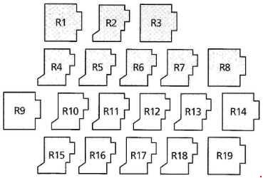
| Position | Amperage [A] | Protected circuit / function |
|---|---|---|
| 1 | – | Relay 1 – second radiator cooling fan speed on 2.0/2.3 DOHC, or powered exterior mirrors on 2.8 V6 |
| 2 | – | Relay 2 – first radiator cooling fan speed on 2.0/2.3 DOHC, or powered mirrors on 2.8 V6 |
| 3 | – | Relay 3 – inverter on 2.0/2.3 DOHC, or radiotelephone/catalytic converter control on V6 or turbo diesel |
| 4 | – | Relay 4 – auxiliary heater, air conditioning or seatbelt warning buzzer on 2.8 V6 |
| 5 | – | Relay 5 – radiator cooling fan on V6 or turbo diesel |
| 6 | – | Relay 6 – automatic gearbox |
| 7 | – | Relay 7 – auxiliary heater or second cooling fan speed |
| 8 | – | Relay 8 – headlamp washer system |
| 9 | – | Relay 9 – Scandinavian daytime running lights |
| 10 | – | Relay 10 – vehicle horn |
| 11 | – | Relay 11 – wide-open throttle cut-off |
| 12 | – | Relay 12 – air conditioning |
| 13 | – | Relay 13 – isolation diode on V6 or turbo diesel, not a conventional relay |
| 14 | – | Relay 14 – engine immobiliser electronics |
| 15 | – | Relay 15 – recirculated air flap motor for A/C and auxiliary heating |
| 16 | – | Relay 16 – power-operated rear quarter/vent windows |
| 17 | – | Relay 17 – auxiliary heater |
| 18 | – | Relay 18 – engine cooling system or radiotelephone on V6 |
| 19 | – | Relay 19 – isolation diode or turbo-diesel-specific relay |
Third level – high-current protection and relays
The first seven rows use “*” because the archived source does not assign permanent numerical fuse codes. They represent independently described high-current power links: 50 A heated front screen, 30 A powered windows, 80/50 A diesel glow-plug alternatives, and separate 30/40/40 A cooling fan supplies. Do not assume each starred entry is installed simultaneously.
The following relay positions 20-26 cover auxiliary heating, wipers, secondary air, windscreen heating, petrol fuel pump or diesel glow control, air-conditioning/fans and starter motor power. The physical wiring and relay population depend strongly on engine and build date.
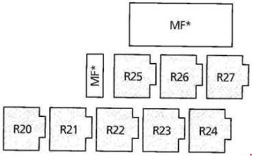
| Position | Amperage [A] | Protected circuit / function |
|---|---|---|
| * | 50 | Unnumbered high-current fuse – electrically heated front windscreen, 50 A |
| * | 30 | Unnumbered high-current fuse – front/rear power windows, 30 A |
| * | 80 | Unnumbered diesel glow-plug high-current fuse, 80 A |
| * | 50 | Alternative diesel glow-plug 50 A link in different engine configuration |
| * | 30 | Unnumbered 30 A second cooling fan speed high-current feed |
| * | 40 | Unnumbered 40 A radiator fan supply, first listed alternative |
| * | 40 | Unnumbered 40 A radiator fan supply, second listed alternative |
| 20 | – | Relay 20 – auxiliary cabin heating |
| 21 | – | Relay 21 – windscreen wiper motor |
| 22 | – | Relay 22 – secondary-air injection or second turbo-diesel glow-plug stage |
| 23 | – | Relay 23 – heated front windscreen |
| 24 | – | Relay 24 – petrol fuel pump or turbo-diesel glow-plug relay |
| 25 | – | Relay 25 – air conditioning on 2.0/2.3 DOHC, first glow-plug stage on turbo diesel or V6 cooling fan |
| 26 | – | Relay 26 – starter motor supply relay |
1995-2006 variations by facelift, powertrain and equipment
Ford Galaxy WGR was sold with petrol 2.0, 2.3 DOHC and 2.8 V6 engines as well as 1.9 TDI diesels. Turbo diesels can have extra glow plugs and auxiliary heating; V6 models may use additional fan, cooling and air-conditioning circuits. European facelift production around 2000 changed wiring and control modules, and some fuse differences also follow transmission, right/left-hand drive, trailer connection, 4×4 equipment and optional heated windscreen.
The Ford factory 2004 owner’s handbook demonstrates the later fuse holder layout with a separate lower numbered strip. Do not merge it with the early 1995-1999 dashboard diagram. In case of uncertainty, the actual fuse label, VIN-specific electrical documentation and original installed fuse rating take precedence.
Common Ford Galaxy Mk1 electrical failures
Cigarette lighter or 12 V outlet has no power: inspect early type 1 position 22 (10 A) or later type 2 position 7 (25 A in 2004 handbook). Also inspect the socket for metal fragments or a damaged USB charger. Optional boot sockets are separately protected by under-seat 76 (15 A).
Heated windscreen stops defrosting: on type 1 the main supply is 27 (50 A); the third level carries separate 50 A high-current protection and a heater relay on type 2. Verify the two windshield heating segments, switch and relay before installing a new fuse.
ABS warning remains lit: inspect type 1 28 and 29 (30 A each) or type 2 9 and 10 (30 A each), together with wheel-speed sensor and ABS control fault codes.
Cabin blower or rear heating fails: check the relevant blower supply, type 1 6/34/39 or type 2 21/22/34 depending on whether the problem affects the front or rear fan. Blower resistor faults may leave only full-speed operation.
Radiator fan does not run: check type 1 engine 58/59 and the fan relays 50/52/54, or later additional circuits in the second and third relay tiers. A jammed fan or burned connector can repeatedly blow a correctly rated fuse.
Central locking or window operation is intermittent: inspect the appropriate type 1 fuses 30, 37 or type 2 2 and 12, plus the door-jamb wiring and module earth connections. A car with optional power quarter windows has extra relay protection.
Related Ford MPVs and first-generation Sharan platform
The later Ford Galaxy Mk2 (2006-2014) uses an entirely different platform and fusebox design. The related Ford S-Max Mk1 (2006-2014) is also a later-generation vehicle. The WGR Galaxy was developed alongside Volkswagen Sharan I and Seat Alhambra I, but each installed engine and model year should be checked against its own factory documentation rather than copying fuse numbers between cars.
Manufacturer documentation: Ford Polska “Ford Galaxy – Instrukcja obslugi”, issue 3370pl09/2004, fuse and relay section, printed pages around 142-148; the complete early type 1 and auxiliary relay charts are retained from the original technical reference.