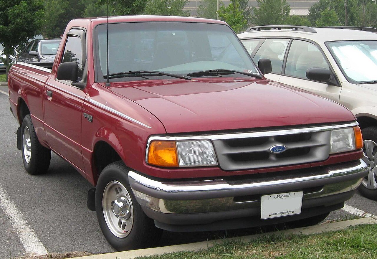
Ford Ranger 1993-1997 – North American version uses a driver-side passenger-compartment fuse panel and an under-hood power-distribution box. Several fuse ratings vary with ABS type, 4×4 equipment and model-year configuration, so repeated positions are intentionally kept as separate rows.
For the following model-year range, see Ford Ranger 1998-2000.
Fuse-box locations
Passenger compartment: on the driver’s side, low on the side of the dashboard / lower dash panel. Engine compartment: the power-distribution box contains the high-current fuses and relays for PCM, fuel pump, wipers, horn and A/C circuits.
Passenger-compartment fuse panel
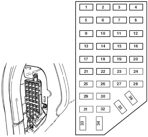
| Position | Rating [A] | Protected component / function |
|---|---|---|
| 1 | 7.5 | Power mirror. |
| 2 | – | Not used. |
| 3 | 15 | Parking lamps. |
| 4 | 10 | Left headlamp. |
| 5 | 10 | Data Link Connector (DLC). |
| 6 | 7.5 | Airbag system, blower relay, EATC. |
| 7 | 7.5 | Illumination switches. |
| 8 | 10 | Right headlamp, fog-lamp relay, Daytime Running Lamps. |
| 9 | 10 | Anti-lock Brake System. |
| 10 | 7.5 | Speed control, Generic Electronic Module (GEM), climate control, brake-shift interlock. |
| 11 | 7.5 | Instrument cluster, warning lamps. |
| 12 | 10 | Windshield washer system, power windows. |
| 13 | 15 | PCM system, stop lamps, 4WD / AWD, anti-lock brake system, speed control. |
| 14 | 20 | Anti-lock Brake System – one equipment variant. |
| 10 | Anti-lock Brake System – alternate equipment variant. | |
| 15 | 7.5 | Airbag, alternator. |
| 16 | 30 | Front wiper. |
| 17 | 25 | Cigarette lighter – one equipment/year variant. |
| 15 | Cigarette lighter – alternate equipment/year variant. | |
| 18 | 15 | Air-conditioning system. |
| 19 | 25 | PCM system, ignition coil. |
| 20 | 7.5 | Anti-theft system, Generic Electronic Module, radio. |
| 21 | 15 | Hazard lamps. |
| 22 | 10 | Turn signals. |
| 23 | – | Not used. |
| 24 | 10 | Starter, anti-theft system. |
| 25 | 7.5 | Speedometer, Generic Electronic Module. |
| 26 | 10 | 4R44E / 4R55E / 4R70W / 5R55E overdrive circuit, Daytime Running Lamps, reversing lamps. |
| 27 | 10 | Under-hood lamp, map lamps, glove-box lamp, dome lamp, visor lamps, 4×4 system. |
| 28 | 7.5 | Generic Electronic Module. |
| 29 | 10 | Audio system. |
| 30 | – | Not used. |
| 31 | – | Not used. |
| 32 | – | Not used. |
| 33 | 15 | Headlamps, Daytime Running Lamps module, instrument cluster. |
| 34 | – | Not used. |
| 35 | – | Not used. |
| 36 | – | Not used. |
Engine-compartment power-distribution box
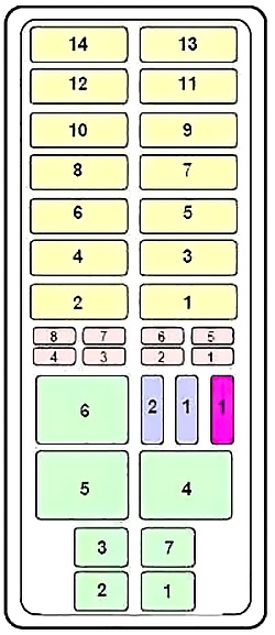
| Position | Rating [A] | Protected component / function |
|---|---|---|
| Maxi fuses | ||
| 1 | – | Not used. |
| 2 | 30 | PCM power feed. |
| 3 | 20 | Fuel system, anti-theft system. |
| 4 | 20 | Headlamps. |
| 5 | 30 | ABS. |
| 6 | 30 | ABS. |
| 7 | – | Not used. |
| 8 | 20 | Parking lamps. |
| 9 | 40 | Blower motor. |
| 10 | 20 | Power locks, power windows, power seat. |
| 11 | 20 | PCM memory, horn. |
| 12 | – | Not used. |
| 13 | 50 | Instrument-panel fuse-panel feed. |
| 14 | 50 | Ignition. |
| Mini fuses | ||
| 1 | 20 | JBL audio system. |
| 2 | 30 | Power point. |
| 3 | 15 | HEGO sensor circuit. |
| 4 | 20 | 4WD system – one equipment variant. |
| 10 | Airbag system – alternate equipment variant. | |
| 5 | 15 | PCM memory power. |
| 6 | 15 | Alternator system. |
| 7 | 10 | Airbag system – one equipment variant. |
| 20 | 4WD system – alternate equipment variant. | |
| 8 | 15 | Daytime Running Lamps / fog lamps / off-road lamps. |
| Relay | ||
| 1 | Relay | Wiper run relay. |
| 2 | Relay | Horn relay. |
| 3 | Relay | Fog-lamp relay. |
| 4 | Relay | Wide-open-throttle A/C relay. |
| 5 | Relay | PCM power relay. |
| 6 | Relay | Fuel-pump relay. |
| 7 | Relay | Wiper high/low relay. |
| Diode | ||
| 1 | Diode | ABS diode. |
| 2 | Diode | PCM diode. |
| Resistor | ||
| 1 | Resistor | RABS resistor. |
Commonly checked circuits
- DLC / diagnostic connector: cabin position 5 – 10 A.
- Cigarette lighter: cabin position 17 – 25 A or 15 A depending on configuration.
- Fuel system: under-hood maxi fuse 3 – 20 A; fuel-pump relay is relay 6.
- ABS: several cabin and under-hood positions differ according to RABS / 4WABS equipment.
FAQ – Ford Ranger 1993-1997 fuses
Why is position 14 shown with two ratings?
Ford used different anti-lock brake configurations. Match the rating to the vehicle’s RABS / 4WABS equipment rather than fitting the higher-amperage fuse automatically.
Where should I start if a scan tool will not power up?
Check cabin position 5 – 10 A, then verify power and ground directly at the Data Link Connector.