
Ford Ranger 1998-2000 – North American version has a driver-side passenger-compartment fuse panel and an engine-compartment power-distribution box. Several circuits changed for the 2000 model year, especially the diagnostic connector, 4×4 and lighting circuits.
Previous: Ranger 1993-1997. Next: Ranger 2001-2003.
Fuse-box locations
Passenger compartment: on the driver’s side of the dashboard, behind the access cover visible with the driver’s door open. Engine compartment: the power-distribution box contains the high-current fuses and relays for PCM, ABS, starter, blower and fuel-pump circuits.
Passenger-compartment fuse panel
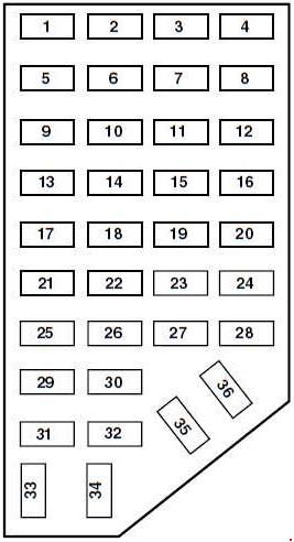
| Position | Rating [A] | Protected component / function |
|---|---|---|
| 1 | 7.5 | Power-mirror switch. |
| 2 | 7.5 | Blower-motor relay, Passenger Airbag Deactivation module, airbag diagnostic monitor. |
| 3 | 7.5 | Left trailer-tow stop / turn circuit. |
| 4 | 10 | Left headlamp. |
| 5 | 10 | 1998-1999: Data Link Connector (DLC). |
| 6 | 15 | 2000: overdrive indicator / transmission-related circuit, reversing lamps, Daytime Running Lamps, 4×4. |
| 7 | 7.5 | Right trailer-tow stop / turn circuit. |
| 8 | 10 | Right headlamp, fog-lamp relay. |
| 9 | 7.5 | Brake Pedal Position switch. |
| 10 | 7.5 | Speed-control servo / amplifier, Generic Electronic Module, shift actuator, blend-door actuator, A/C-heater assembly, turn-signal / flasher circuits. |
| 11 | 7.5 | Instrument cluster, Daytime Running Lamps, RABS resistor. |
| 12 | – | Not used. |
| 13 | 20 | Brake Pedal Position switch. |
| 14 | 20 | Rear Anti-lock Brake System module. |
| 10 | Four-Wheel Anti-Lock Brake System module and main relay. | |
| 15 | 7.5 | Airbag indicator, alternator indicator, instrument cluster. |
| 16 | 30 | Front wiper motor, wiper high/low relay, wiper run/park relay. |
| 17 | 25 | Cigarette lighter; in 2000 also Data Link Connector. |
| 18 | 15 | Driver-unlock relay, all-lock / all-unlock relay circuits. |
| 19 | 25 | PCM power diode, ignition, Passive Anti-Theft System. |
| 20 | 7.5 | Remote Anti-Theft Personality module, Generic Electronic Module, radio. |
| 21 | 15 | Hazard lamps. |
| 22 | 20 | Auxiliary power point. |
| 23 | – | Not used. |
| 24 | 7.5 | Clutch Pedal Position switch, starter-interrupt relay, anti-theft system. |
| 25 | 7.5 | 1998-1999: Generic Electronic Module, instrument cluster. |
| 26 | 10 | Battery-saver relay, electronic shift relay, interior-lamp relay, power-window relay, electronic shift-control module; in 2000 also dome/map lamp, GEM and instrument cluster. |
| 27 | 15 | 1998-1999: electronic shift-control circuits, reversing lamps, Daytime Running Lamps, transmission-control switch and pulse-vacuum hublock circuit. |
| 28 | 7.5 | Generic Electronic Module, radio. |
| 29 | 15 | Radio. |
| 30 | 10 | 1999-2000: RABS test connector. |
| 15 | 1998: parking-lamp / trailer-tow relay. | |
| 31 | – | Not used. |
| 32 | – | Not used. |
| 33 | 15 | Headlamps, Daytime Running Lamps module, instrument cluster. |
| 34 | – | Not used. |
| 35 | 15 | 1999: parking-lamp / trailer-tow relay. |
| 10 | 1998: RABS test connector. | |
| 36 | – | Not used. |
Engine-compartment power-distribution box
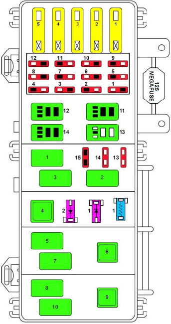
| Position | Rating [A] | Protected component / function |
|---|---|---|
| 1 | 50 | Instrument-panel fuse panel. |
| 2 | 40 | Blower-motor relay. |
| 3 | 50 | Four-Wheel Anti-Lock Brake System module. |
| 4 | 20 | Power windows. |
| 5 | 50 | Ignition relay, starter relay. |
| Mini fuses | ||
| 1 | 10 | A/C relay. |
| 2 | 20 | Auxiliary power point. |
| 3 | 20 | Electronic shift relay and electronic shift-control module. |
| 4 | 20 | 2000: fog lamps and Daytime Running Lamps. |
| 15 | 1998-1999: fog lamps and Daytime Running Lamps. | |
| 5 | 15 | 2000: trailer-tow lamps. |
| 10 | 1998: airbag diagnostic monitor. | |
| 6 | 10 | Powertrain Control Module. |
| 7 | 30 | Four-Wheel Anti-Lock Brake System module. |
| 8 | 30 | PCM relay. |
| 9 | 20 | Fuel-pump relay and Remote Anti-Theft Personality module. |
| 10 | 15 | Horn relay. |
| 11 | 15 | Parking-lamp relays and main light switch. |
| 12 | 30 | Main light switch and multifunction switch. |
| 13 | 15 | Heated oxygen sensor, EGR vacuum regulator, EVR solenoid, camshaft-position sensor and canister-vent solenoid. |
| 14 | 30 | Alternator voltage regulator. |
| 15 | – | Not used. |
| Relay | ||
| 1 | Relay | Wiper relay. |
| 2 | Relay | A/C relay. |
| 3 | Relay | Wiper high/low relay. |
| 4 | Relay | PCM power relay. |
| 5 | Relay | Fuel-pump relay. |
| 6 | Relay | Starter relay. |
| 7 | Relay | Horn relay. |
| 8 | Relay | 1999-2000: fog-lamp control relay; 1998: washer-pump relay. |
| 9 | Relay | Blower-motor relay. |
| 10 | Relay | 1999-2000: fog-lamp isolation relay; 1998: fog-lamp relay. |
| 11 | Relay | Not used. |
| 12 | Relay | Not used. |
| 13 | Relay | Parking-lamp / trailer-tow relay. |
| 14 | Relay | Washer-pump relay. |
| Resistor | ||
| 1 | Resistor | RABS resistor. |
| Diodes | ||
| 1 | Diode | RABS diode. |
| 2 | Diode | Electronic engine-control diode. |
Commonly checked circuits
- OBD / DLC: cabin position 5 – 10 A on 1998-1999; on 2000 vehicles the DLC is associated with position 17.
- Cigarette lighter: cabin position 17 – 25 A.
- Fuel pump: engine mini fuse 9 – 20 A and relay 5.
- ABS: cabin position 14 has separate RABS and 4WABS ratings; the engine box also contains a 50 A 4WABS feed.
FAQ – Ford Ranger 1998-2000 fuses
Why can the OBD-II connector and cigarette lighter fail together on a 2000 Ranger?
For 2000, both are associated with cabin position 17. On 1998-1999 vehicles the DLC is listed separately at position 5.
Can I use the 2001-2003 diagram for a 2000 truck?
No. The boxes look related, but Ford changed several circuit assignments and relay functions.