
This guide covers the pre-facelift Ford Ranger T6, referred to on Bezpieczniki.net as the Ranger Mk3, built from 2011 to the first half of 2015. It uses an engine-compartment fuse box with positions F1-F51 and relays R1-R27, plus a passenger-compartment panel with fuses F56-F89. Selected commercial or special-equipment vehicles can also have an auxiliary fuse and relay box.
The 2015 cut-off matters. From June 2015 Ford introduced the facelifted Ranger and revised fuse-box variants, so the tables below should not automatically be applied to later trucks. The previous generation uses a different arrangement described in the Ford Ranger Mk2 2006-2011 guide.
Ford’s factory documentation for the pre-facelift T6 distinguishes gasoline and diesel engines, 4×4, rear differential lock, heated windshield, trailer equipment and special-use configurations. Several fuse ratings therefore depend on engine or equipment.
Fuse box locations – Ford Ranger T6
Main engine-compartment fuse box: contains fuses F1-F51 and relays R1-R27. It protects ABS, the 4×4 system, starter, engine management, wipers, air conditioning, heated windshield and the supply to the cabin fuse box.
Passenger-compartment fuse box: located low in the dashboard on the driver’s side. On left-hand-drive vehicles, access is through the small storage panel near the steering wheel. It contains positions F56-F89.
Auxiliary fuse box: fitted only to selected commercial or special-equipment versions. It contains fuses 1-12 and relays R1-R9.
Engine-compartment fuse box F1-F51
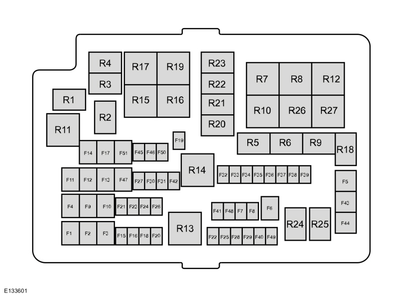
The F1-F51 layout is characteristic of the pre-facelift T6. F3 and F15 each appear twice because their rating and function depend on the engine type.
| Fuse | Rating | Protected component / function |
|---|---|---|
| F1 | 60 A | Passenger-compartment fuse box supply – battery |
| F2 | 60 A | Passenger-compartment fuse box supply – battery |
| F3 – gasoline | 50 A | Engine cooling fan |
| F3 – diesel | 60 A | Glow plug control module |
| F4 | 40 A | ABS module |
| F5 | 30 A | Front and rear power windows |
| F6 | 25 A | 4×4 system motor ground |
| F7 | – | Not used |
| F8 | – | Not used |
| F9 | 20 A | Power seat |
| F10 | 25 A | Front power windows |
| F11 | 30 A | Heater and A/C blower motor |
| F12 | 25 A | 4×4 system motor power |
| F13 | 20 A | Starter solenoid |
| F14 | 20 A | Heated rear window |
| F15 – gasoline | 10 A | Flex-Fuel pump |
| F15 – diesel | 20 A | Vaporizer glow plug |
| F16 | 10 A | A/C compressor clutch |
| F17 | 25 A | Front power windows |
| F18 | 25 A | Windshield wiper motor |
| F19 | 25 A | Windshield wiper motor ground |
| F20 | 20 A | Cigarette lighter |
| F21 | 15 A | Horn |
| F22 | 15 A | Fuel injectors, Flex-Fuel valve – depending on engine |
| F23 | 10 A | Rear differential lock solenoid |
| F24 | 20 A | Auxiliary power point in instrument panel / upper console |
| F25 | 15 A | Ignition coils, air temperature and flow sensor, glow-plug module, VCV, EVRV – depending on engine |
| F26 | 7.5 A | Engine control module (ECM) |
| F27 | 10 A | Transmission control module (TCM) |
| F28 | 10 A | Heated exhaust sensors, universal oxygen sensor, relay coils |
| F29 | 15 A | Engine control module (ECM) |
| F30 | 15 A | Battery monitoring sensor |
| F31 | 20 A | Auxiliary power point at rear of console |
| F32 | 5 A | A/C pressure switch / sensor |
| F33 | 10 A | Transmission control module (TCM) |
| F34 | 5 A | PTC auxiliary heater / Crew Chief module / spare – depending on version |
| F35 | 20 A | Passenger-compartment fuse box supply – ignition |
| F36 | 5 A | ABS module |
| F37 | 10 A | Headlamp leveling |
| F38 | 20 A | Heated seat |
| F39 | 10 A | Power mirrors |
| F40 | – | Not used |
| F41 | 10 A | Heated exterior mirrors |
| F42 | 10 A | Alarm horn |
| F43 | 30 A | Heated windshield – right-hand side |
| F44 | 30 A | Heated windshield – left-hand side |
| F45 | 25 A | ABS module |
| F46 | 20 A | Auxiliary power point in floor console |
| F47 | 20 A | Trailer tow module |
| F48 | – | Not used |
| F49 | – | Not used |
| F50 | 5 A | Ignition relay, relay coils |
| F51 | 30 A | Rear power windows |
The heated windshield is split into two independently protected halves: F43 30 A for the right-hand side and F44 30 A for the left-hand side. A similar arrangement is used in the Ford Kuga Mk1.
Engine-compartment relays R1-R27
Relays R1-R27 are located in the same box as fuses F1-F51. An older version of the article incorrectly described R14 as a charging-system relay; Ford’s factory documentation identifies R14 as the ignition relay.
| Relay | Function |
|---|---|
| R1 | Key interlock |
| R2 | Wiper on/off |
| R3 | Horn |
| R4 | A/C compressor clutch |
| R5 | Differential lock |
| R6 | Wiper high/low speed |
| R7 | Cooling fan low speed |
| R8 | Cooling fan high speed |
| R9 | Flex-Fuel pump / vaporizer glow plug |
| R10 | Heated rear window |
| R11 | Heated windshield |
| R12 | Not used |
| R13 | ECM power hold |
| R14 | Ignition |
| R15 | 4WD motor 2 – clockwise rotation |
| R16 | 4WD motor 1 – counterclockwise rotation |
| R17 | 4WD system motor |
| R18 | Security horn |
| R19 | Starter |
| R20 | Not used |
| R21 | Not used |
| R22 | Not used |
| R23 | Not used |
| R24 | Not used |
| R25 | Not used |
| R26 | Blower motor |
| R27 | Power seat |
Passenger-compartment fuse box F56-F89
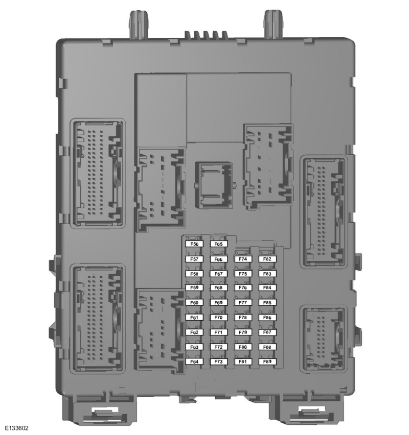
The numbering starts at F56 because F1-F51 belong to the engine-compartment box. The missing F52-F55 positions in the passenger panel are therefore normal.
| Fuse | Rating | Protected component / function |
|---|---|---|
| F56 | 20 A | Fuel pump |
| F57 | – | Not used |
| F58 | – | Not used |
| F59 | 5 A | Passive Anti-Theft System (PATS) |
| F60 | 10 A | Interior lighting, driver-door switch panel, ambient lighting, scuff-plate lamps, automatic transmission, footwell lighting |
| F61 | – | Not used |
| F62 | 5 A | Rain sensor module |
| F63 | – | Not used |
| F64 | – | Not used |
| F65 | – | Not used |
| F66 | 20 A | Driver door unlock, central double locking |
| F67 | 5 A | Stop-lamp switch |
| F68 | – | Not used |
| F69 | 5 A | Instrument cluster, integrated control panel (ICP), vehicle tracking and immobilization module |
| F70 | 20 A | Central locking |
| F71 | 5 A | Air conditioning |
| F72 | 7.5 A | Alarm horn |
| F73 | 5 A | OBD-II diagnostic connector |
| F74 | 20 A | High-beam headlamps |
| F75 | 15 A | Front fog lamps |
| F76 | 10 A | Reversing lamp, rear-view mirror |
| F77 | 20 A | Washer pump |
| F78 | 5 A | Ignition switch |
| F79 | 15 A | DIN/FSAO audio system, multifunction display |
| F80 | 20 A | Multifunction display, premium audio system, BVC module |
| F81 | 5 A | Interior motion sensor |
| F82 | 20 A | Washer pump ground |
| F83 | 20 A | Central locking ground |
| F84 | 20 A | Driver door unlock, central double-locking ground |
| F85 | 7.5 A | Instrument cluster, parking sensors, rear-view camera, manual A/C, rear-view mirror, tracking/immobilization module |
| F86 | 10 A | Airbag system, passenger-airbag deactivation indicator |
| F87 | 5 A | Tachograph |
| F88 | – | Not used |
| F89 | – | Not used |
F82-F84 are worth noting because Ford uses them on the ground side of the washer and central-locking circuits. That is less common than a conventional positive-side fuse arrangement and can be important during diagnosis.
Auxiliary fuse box – if equipped
Not every Ranger has this panel. It was intended mainly for special commercial equipment and can supply auxiliary high beams, work lamps, an LED warning beacon and additional power outlets.
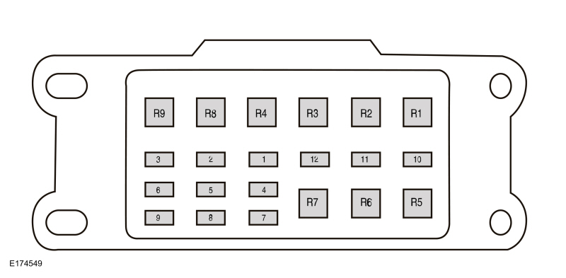
| Fuse | Rating | Protected component / function |
|---|---|---|
| 1 | 25 A | Auxiliary high-beam lamps |
| 2 | 15 A | Position lamp |
| 3 | 10 A | LED warning beacon |
| 4 | 15 A | Work lamps |
| 5 | 20 A | Spare |
| 6 | 20 A | Auxiliary power point |
| 7 | 15 A | Reversing lamp |
| 8 | 15 A | Turn signals and stop lamps |
| 9 | 5 A | Crew Chief system |
| 10 | 5 A | Ground disconnect / isolator fuse |
| 11 | – | Not used |
| 12 | – | Not used |
Auxiliary-box relays
| Relay | Function |
|---|---|
| R1 | Work lamps |
| R2 | LED warning beacon |
| R3 | Spare |
| R4 | Position lamp |
| R5 | Left turn signal |
| R6 | Right turn signal |
| R7 | Stop lamp |
| R8 | Not used |
| R9 | Not used |
Gasoline and diesel differences
Although the European Ranger T6 is most commonly associated with Duratorq diesel engines, Ford’s factory fuse documentation also covers gasoline versions. That is why F3 and F15 appear twice in the main table.
F3 is 50 A for the engine cooling fan on gasoline models and 60 A for the glow-plug control module on diesel models. F15 is 10 A for the Flex-Fuel pump on gasoline versions and 20 A for the vaporizer glow plug on diesel versions.
F25 15 A is also engine-dependent. On diesel versions, the circuit includes the glow-plug module, VCV and EVRV. Although the Ford Transit Mk7 also used Duratorq diesels, its fuse-box architecture and numbering are completely different.
4×4 system and rear differential lock
The four-wheel-drive system has several dedicated circuits. F6 25 A protects the ground side of the 4WD motor and F12 25 A its power supply. Relays R15, R16 and R17 control motor operation and direction.
The rear differential lock has a separate circuit: F23 10 A supplies the lock solenoid and R5 is the differential-lock relay. If only the rear differential lock is affected, F6 and F12 are not the first circuits to check because they belong to the 4WD shift motor system.
Why can a 2015 Ranger use a different fuse diagram?
From June 2015 Ford introduced revised electrical documentation for the facelifted Ranger. Later vehicles can use different fuse-box types, an additional high-current box beneath the main panel and different assignments.
Because first-registration year does not always match production date, a 2015 truck should be identified by build date and physical fuse-box layout before applying the F1-F51 and F56-F89 tables above.
Ranger T6 vs North American Ranger 2004-2012
The North American Ford Ranger 2004-2012 is not a duplicate of this article. It uses different engines, fuse boxes and numbering despite overlapping model years.
FAQ – Ford Ranger Mk3 2011-2015 fuses
Why is F3 rated at 50 A or 60 A?
It depends on the engine. F3 is 50 A for the cooling fan on gasoline versions and 60 A for the glow-plug control module on diesel versions.
Why does F15 have different ratings?
Ford uses the same position for different engine-specific circuits: 10 A for the Flex-Fuel pump on gasoline models and 20 A for the vaporizer glow plug on diesel models.
Why do the cabin fuses start at F56?
The numbering continues from the main under-hood box. The engine-compartment box uses F1-F51, while the passenger panel begins at F56 and ends at F89.
What are F43 and F44 for?
They separately protect the two halves of the heated windshield: F43 30 A for the right-hand side and F44 30 A for the left-hand side.
Does every Ranger have the auxiliary 12-fuse box?
No. It is fitted only to selected special-equipment or commercial configurations.
Does this diagram apply to a late-2015 or 2016 facelift Ranger?
Do not assume it does. Ford revised the electrical system and fuse-box variants from mid-2015. This guide covers the pre-facelift T6 arrangement.
Is F51 always the rear power-window fuse?
In the European documentation for the configuration covered here, F51 is 30 A for the rear power windows. Other markets and later T6 variants can use the same position differently.