
Peugeot 205 GTI and CTI models used a 14-slot fuse board in the passenger compartment, with separate under-bonnet protections on cars equipped with ABS, electronic fuel injection or certain cooling systems. The tables below reproduce the source guide’s 14 main positions and four additional engine-bay circuit ratings. The 1986-1988 GTI / CTI reference arrangement is used for the central table; these cars changed electrically across production, so it is not a claim that every 205 from 1986 to 1998 has the same fuse assignments.
Where is the fuse box in a Peugeot 205 GTI or CTI?
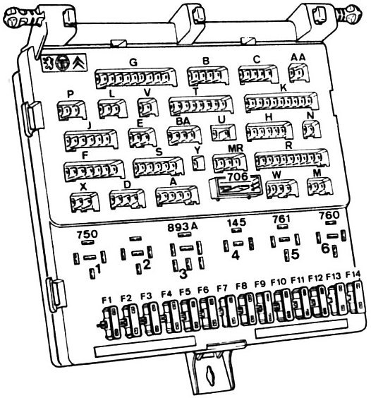
Interior board: Switch the ignition off, open the glovebox on left-hand-drive vehicles and look immediately above the glovebox at the left side of the fascia. Depress the spring clip and allow the fuse board to drop down for access. Some later trim and market versions differ; use the vehicle’s actual diagram and labels rather than assuming all dashboard panels open identically. The board has 14 numbered blade-fuse positions and several rear wiring connectors.
Additional fuses: On GTI models, an in-line fuel-pump fuse may be fitted close to the back of the main board. Depending on year and engine, other in-line fuses can be placed beside the radiator, on the bulkhead or near the horn. These are separate circuits and are not necessarily grouped into one numbered engine-bay box; their physical positions must be confirmed using the engine-specific manual.
Peugeot 205 GTI / CTI 14-position fuse box diagram
The larger diagram identifies the same 14-position fuse board from the source article, with connector locations also visible. The table preserves the original ratings, including spare positions 4 and 6. The rated 15 A fuel-pump entry refers to the relevant circuit listing and does not replace an additional in-line fuse where a particular GTI’s wiring uses one.
| Pozycja | Amperaż [A] | Chroniony obwód / funkcja |
|---|---|---|
| 1 | 10 | Reversing lamps and rev counter |
| 2 | 25 | Direction indicators, heater blower motor, oil pressure and temperature gauges, heated seats, fuel gauge, coolant temperature gauge, battery charging warning, oil pressure, braking system, temperature and low coolant warning lamps |
| 3 | 25 | Front windscreen wipers and washer, brake lamps, headlamp washer, ignition-switched radio and accessory circuits |
| 4 | – | SPARE – Unused spare fuse position |
| 5 | 10 | Hazard warning lights and flasher |
| 6 | – | SPARE – Unused spare fuse position |
| 7 | 25 | Cigarette lighter, clock, interior and boot lighting, central door locking and radio |
| 8 | 25 | Horns |
| 9 | 20 | Electrically operated windows |
| 10 | 5 | Rear fog lamp |
| 11 | 5 | Right-hand tail lamp and registration-plate lighting |
| 12 | 5 | Left-hand tail lamp |
| 13 | 5 | Instrument panel illumination and side/position lamps |
| 14 | 15 | Fuel pump on the corresponding petrol-injection installation |
Additional engine-bay fuses for ABS, cooling and oxygen sensor
The four entries below are additional circuit protections rather than numbered locations in the 14-fuse board. Their exact positions depend on engine, installed ABS and model year. No numbered engine-bay drawing is supplied for these scattered holders; a universal location diagram would be misleading.
| Pozycja | Amperaż [A] | Chroniony obwód / funkcja |
|---|---|---|
| ABS | 30 | ABS main hydraulic and electrical system protection, when fitted |
| ABS ECU | 15 | ABS electronic control unit supply, if the car is equipped with ABS |
| FAN | 30 | Radiator cooling fan circuit; fuse position depends on engine and installed wiring |
| O2 | 10 | Lambda / oxygen sensor on equipped petrol-injection engines |
GTI / CTI differences across model years
The table above matches the early GTI and CTI documentation, notably the 1986-1988 list. Published service material for 1988-1989 GTI and CTI also describes a 20 A alternative for fuse 7 (lighter and central locking) rather than 25 A, adds rear-window heating to fuse 8, and can list fuse 12 as a spare 5 A position instead of the left tail lamp. Fuse 3 also has an expanded list covering additional lighting and storage-tray circuits. These are genuine alternate electrical configurations, not a reason to interchange ratings on the same car.
On later Peugeot 205 models, including some 1995-1998 cars, the 14-position numbering may remain even though the electrical allocation changes; for example, the 12 V lighter can move from early fuse 7 to late fuse 8. Verify the exact model and as-built panel before starting diagnostics.
What to check if the lighter, fuel pump or horn fails
Early GTI cigarette lighter: Fuse 7 is 25 A in this reference, serving the clock, interior and boot lamps, door locks and radio. Certain 1988-1989 cars use the 20 A version of this circuit. Horn: Fuse 8 (25 A) is associated with the horn circuit in the table. Wipers and stop lamps: Fuse 3 (25 A) serves the windscreen wash/wipe and brake light circuits.
Fuel injection: The chart lists fuse 14 (15 A) for fuel pump protection, while some GTI wiring variants place an additional in-line pump fuse behind the board. If the engine will not start, check both the actual installed fuse carrier and the pump relay and wiring before blaming the pump itself.
Other Peugeot fuse box generations
Use the Peugeot 205 1995-1998 fuse diagram for the late 14-slot circuit assignments, and the Peugeot 106 II 1996-2003 fuse guide for a smaller successor-era Peugeot with a different three-box electrical arrangement.
Technical basis: Peugeot 205 body electrical system service chapter, GTI/CTI 1986-1988 and 1988-1989 fuse charts, plus the existing 14-position GTI / CTI guide. Check the particular market and engine before selecting any fuse.