
The Volvo S70 (1998-1999) shares much of its P80 electrical architecture with the first-generation V70 and C70, but engine, market, alarm and optional-equipment specifications affect individual circuits. The 11C central electrical unit provides numbered blade-fuse circuits and resetting circuit breakers. Separate 11A and 11B groups inside the engine bay protect high-current and engine-control equipment. The tables preserve every original fuse, breaker and relay row, including equipment-specific locations associated only with the C70 convertible rather than incorrectly assigning those slots to the S70.
Where are the Volvo S70 fuse boxes?
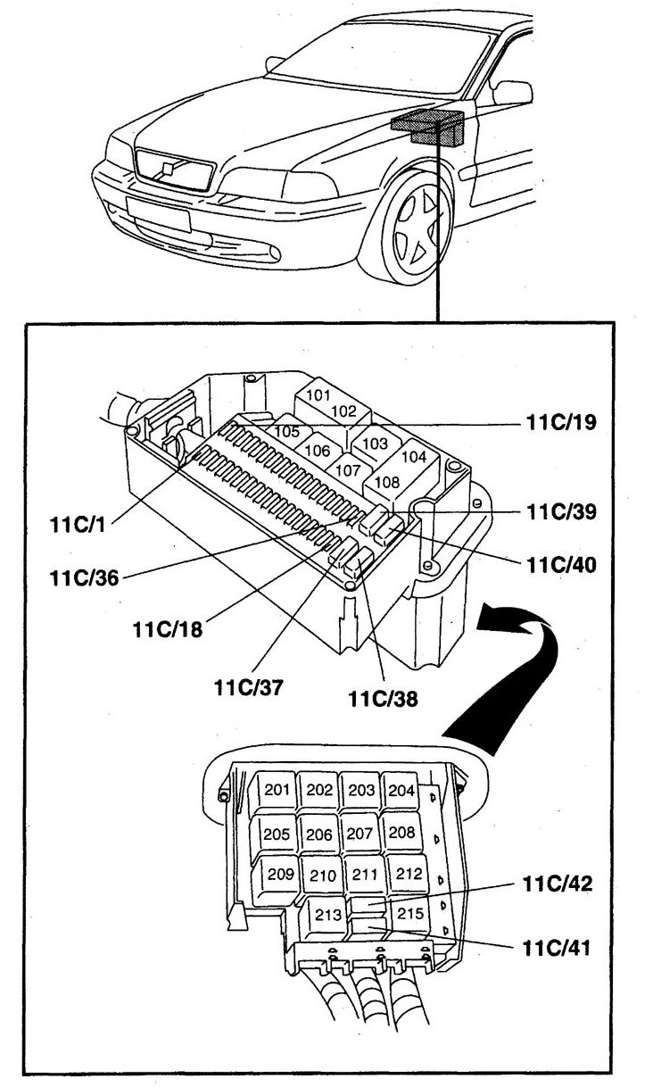
Switch the ignition off, lift the bonnet and find the central electrical unit (11C) towards the rear of the engine compartment near the windscreen on the driver’s side. Release the cover clips carefully and lift the lid to expose the smaller fuses and relay arrangement. On different right-hand-drive or destination-market cars, compare the physical panel and cover legend before identifying a circuit.
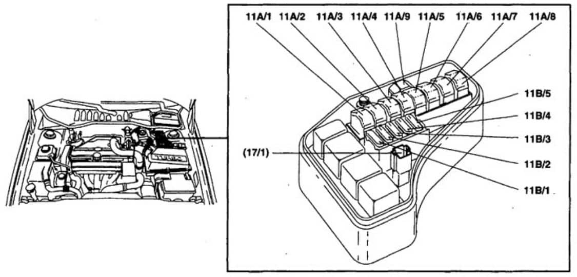
The relay/main fuse carrier (11A and 11B) is a separate covered under-bonnet block close to the other engine-compartment electrical equipment. It carries large high-current links for the radiator fan, starter and ABS and smaller engine control/injection fuses. The cover identifies which section is 11A and which is 11B. Do not treat a high-current bolted link like a small replaceable fuse blade.
Central electrical unit 11C – fuses 1-36
The full-size drawing below is the same model-family 1998 11C unit layout as the original smaller illustration, with the 11C markings made easier to inspect. The table retains specific positions for S70/V70 and optional equipment on related C70 variants. Position 11C/30 is the 15 A lighter feed in this detailed service layout, but some 1998 North American owner-handbook fuse listings leave slot 30 blank; the installed cover takes precedence.
| Pozycja | Amperaż [A] | Chroniony obwód / funkcja |
|---|---|---|
| 11C / 1 | – | Not assigned in this S70 diagram |
| 11C / 2 | 10 | Central locking / anti-theft controller, AW50-42 driving mode switch and Road Traffic Information (RTI) control module |
| 11C / 3 | 10 | Anti-lock braking system (ABS) control module |
| 11C / 4 | 10 | Immobiliser |
| 11C / 5 | 15 | Climate-control system and data-link diagnostic connector (DLC) |
| 11C / 6 | 20 | Central locking and anti-theft controller, alarm siren and movement detector on equipped S70/V70 cars |
| 11C / 7 | 15 | Radio / factory amplifier |
| 11C / 8 | 15 | Immobiliser, instrument cluster and headlamp switch |
| 11C / 9 | 20 | Heated rear seat (S70/V70), or audio amplifier on related C70 equipment |
| 11C / 10 | 15 | Ignition switch |
| 11C / 11 | 10 | Stop / brake lamps |
| 11C / 12 | 20 | Engine coolant heater on diesel; C70-specific amplifier circuit may vary by model |
| 11C / 13 | 15 | Turn indicators, hazard warning flashers, headlamp flash, central locking / alarm module, remote alarm and glass-break detector |
| 11C / 14 | 30 | Heated rear window and heated exterior mirrors |
| 11C / 15 | 10 | Courtesy, glovebox, footwell, open-door and boot lamps, belt reminder and optional RTI display / CD / controller |
| 11C / 16 | 30 | Power antenna, CD player, trailer electrical socket (S70/V70) and optional accessories |
| 11C / 17 | 20 | Front fog lamps |
| 11C / 18 | 10 | Key reminder and central locking / anti-theft controller |
| 11C / 19 | 15 | Left high-beam headlamp and optional equipment |
| 11C / 20 | 15 | Right high-beam headlamp and high-beam warning light |
| 11C / 21 | 15 | Left dipped-beam headlamp |
| 11C / 22 | 15 | Right dipped-beam headlamp |
| 11C / 23 | 10 | Parking and tail lamps plus licence-plate lighting |
| 11C / 24 | 10 | Parking and tail lamps and bulb-failure warning sensor |
| 11C / 25 | 10 | Rear fog lamp and warning indicator |
| 11C / 26 | 15 | Headlamp / exterior lighting switch |
| 11C / 27 | 15 | Reversing lamps and direction indicators |
| 11C / 28 | 25 | Front and optional rear seat heating on S70/V70 |
| 11C / 29 | 10 | Terminal 15/4 supply: rear-window demister, heated mirrors, seat belt warning, cruise, bulb failure sensor, alarm, shift interlock, exhaust temperature sensing, diesel coolant heater or C70 towing wiring |
| 11C / 30 | 15 | Front cigarette lighter / 12 V outlet, optional RTI control module and RTI CD/display (15 A on this service layout; other markets may differ) |
| 11C / 31 | 25 | Climate control system |
| 11C / 32 | 10 | Radio / amplifier supply |
| 11C / 33 | 15 | Terminal X (15/8): headlamp beam-width control and rear windscreen wash/wipe circuits |
| 11C / 34 | 25 | Horn, front windscreen washer/wipers and headlamp washers/wipers |
| 11C / 35 | 10 | Instrument and control panel illumination, ashtray light and optional power sunroof; C70 rear-view mirror variants |
| 11C / 36 | 15 | Rear cigarette lighter / 12 V socket and electric seats |
Central electrical unit 11C – circuit breakers and additional positions 37-42
Positions 37, 39 and 40 are associated with automatic resetting circuit breakers for windows, sunroof or powered seats. They do not have a conventional blade-fuse amperage in the original listing. Positions 38, 41 and 42 are documented in the shared C70/S70/V70 reference and include some C70-only uses; the convertible roof positions 41 and 42 do not belong to an S70 saloon.
| Pozycja | Amperaż [A] | Chroniony obwód / funkcja |
|---|---|---|
| 11C / 37 | – | Automatic circuit breaker for power windows, sunroof, powered or folding mirrors and heated rear window/mirrors on applicable non-convertible cars |
| 11C / 38 | – | Power-window circuit position listed for the related C70; check S70 equipment, not a second automatic fuse by assumption |
| 11C / 39 | – | Automatic circuit breaker for left-hand / driver’s electric seat |
| 11C / 40 | – | Automatic circuit breaker for right-hand / passenger electric seat |
| 11C / 41 | – | C70 convertible soft-top actuator position only – not applicable to S70 saloon |
| 11C / 42 | – | C70 convertible soft-top electrical operation only – not applicable to S70 saloon |
Main relay group – positions 15-18
The detailed electrical diagram used by this older S70 article associates positions 15-18 with cooling, starter and climate equipment, whereas the general 1998 S70/V70 owner’s handbook describes the first two relays differently. This reflects different service descriptions and vehicle configurations, not a reason to exchange relays by position without verification.
| Pozycja | Amperaż [A] | Chroniony obwód / funkcja |
|---|---|---|
| 15 | – | Electric engine cooling fan relay in this detailed service-layout variant; some 1998 owner handbooks call 15 the system relay |
| 16 | – | Unassigned in the source S70 layout; some 1998 market handbooks show the air-pump relay here |
| 17 | – | Starter motor relay |
| 18 | – | Air-conditioning relay |
Under-bonnet fuse and relay box – 11A/1-9 and 11B/1-5
High-current positions 11A/1-9 provide power distribution, including an optional 80 A diesel glow-plug link at 11A/9. The 11B/1-5 group supplies ignition, engine management, fuel pump, injectors and air-conditioning control. Position 11B/3 has 20 A on the listed petrol installation or 15 A on the diesel variant. Both values are retained and should not be treated as interchangeable.
| Pozycja | Amperaż [A] | Chroniony obwód / funkcja |
|---|---|---|
| 11A / 1 | 60 | 11A/1 – Engine cooling fan main power feed |
| 11A / 2 | 50 | 11A/2 – Overload relay power for 11C/26-29 and 11C/33-37 |
| 11A / 3 | 50 | 11A/3 – Starter motor, secondary-air injection (PAIR) pump and diesel coolant heater equipment |
| 11A / 4 | 50 | 11A/4 – ABS controller high-current feed |
| 11A / 5 | 50 | 11A/5 – Main headlamp relay and bulb-failure monitoring |
| 11A / 6 | 60 | 11A/6 – Supply to 11C/5-10 |
| 11A / 7 | 50 | 11A/7 – Supply to 11C/11-17 and 11C/39-40 |
| 11A / 8 | 60 | 11A/8 – Power to 11B/1 and 11B/2-5 via the fuel injection main relay |
| 11A / 9 | 80 | 11A/9 – Diesel glow plugs 1-5 via the glow-plug relay; 80 A where fitted |
| Engine compartment 11B – smaller injection and control-circuit fuses | ||
| 11B / 1 | 10 | 11B/1 – Ignition switch, engine control module (ECM), AW50-42 transmission control and Motronic 4.3/4.4 injection main relay |
| 11B / 2 | 10 | 11B/2 – ECM, injectors, idle air control (IAC), MAF sensor, diesel injection pump and injection timing valve |
| 11B / 3 | 20 (15 olej napędowy) | 11B/3 – Fuel pump, ignition coil/ignition discharge module; on diesels glow-plug relay, coolant heating, turbo boost and EGR/air preheating equipment (20 A petrol, 15 A diesel) |
| 11B / 4 | 10 | 11B/4 – AW50-42 automatic transmission control module |
| 11B / 5 | 10 | 11B/5 – A/C relay, upstream and downstream oxygen sensors, EVAP purge and cut-off controls, PAIR air injection pump/solenoid, turbo control and optional PTC air heater |
1998-1999, diesel and equipment-dependent circuits
The S70 was sold with different engine and emission-control configurations, both manual and AW50-42 automatic gearboxes, anti-theft equipment, optional heated seats and RTI navigation. This reference also contains codes shared with the C70; those convertible-only positions are explicitly marked. For 1998 North American cars, the owner handbook and the more detailed 11C circuit listing may differ in slot occupation, notably at positions 6, 12 and 30. Match the actual model-year label before selecting a rating.
Which S70 fuse protects the 12 V outlet, fuel pump and headlights?
Front cigarette lighter: 11C/30 is 15 A in the detailed source listing; the rear socket, where fitted, is associated with 11C/36 (15 A). On some North American 1998 variants the fuse 30 position is not occupied, so check the panel itself before assuming that rating.
Fuel pump and ignition: 11B/3 is 20 A in petrol configurations and 15 A in listed diesel variants; the 11A/8 main supply is rated 60 A. Do not jump or oversize fuel-system fuses. Headlights: 11C/21 and 11C/22 are the separate 15 A left and right dipped beams. Heated rear glass: 11C/14 (30 A) also supplies heated mirrors.
Related Volvo V70 and predecessor 850
The Volvo V70 I (1998) uses a related 1998 system with its own general owner-handbook layout and wagon-specific circuits. Earlier cars are covered by the Volvo 850 (1993-1997) fuse and relay guide, in which several fuse functions differ across model years.
Technical basis: Volvo S70/C70/V70 1998-1999 detailed central electrical unit and engine-compartment distribution listing, cross-checked with Volvo S70/V70 1998 owner’s handbook, pages 102-104. Country-specific fuse occupations must be checked on the actual vehicle.