
The first-generation Volvo V70 estate (1998) uses two principal fuse carriers under the bonnet: a relay/main fuse box and a supplementary fuse box that contains the 40 numbered interior and accessory circuits. The 1998 Volvo S70/V70 owner’s handbook is used for the base specification. This guide preserves all 14 numbered main fuses, four associated relay positions and all 40 supplementary fuse positions, including three resetting circuit breakers for windows and power seats. North American and diesel-market electrical installations may differ.
Where are the 1998 Volvo V70 fuse boxes?
Turn the ignition off and open the bonnet. The relay/main fuse box is a covered high-current distribution carrier in the engine compartment. Release its latches and lift the cover to inspect fuses 1-14 and relays 15-18. A nearby supplementary fuse box has a separate cover and holds the smaller fuses 1-40, which are referenced independently from the main block. Match the diagram and labels on the lid of the exact car.
With a vehicle of this age, cover clips can be fragile and contacts may have corroded. Main fusible links are high-current service components; if one is open, locate the electrical fault rather than repeatedly replacing it.
Relay/main box – relay positions 15-18
The 1998 Volvo owner handbook identifies the system relay, secondary air pump, starter and air-conditioning relay. Their positions share the same housing as the high-current fuse set.

| Pozycja | Amperaż [A] | Chroniony obwód / funkcja |
|---|---|---|
| 15 | – | Main electrical system relay |
| 16 | – | Secondary air-injection pump relay |
| 17 | – | Starter motor relay |
| 18 | – | Air-conditioning relay |
Relay/main fuse box – power fuses 1-14
The main fuse table lists the cooling fan, ABS, lights, engine and gearbox electronics, starter, injection and fuel pump. Main fuse 9 is unoccupied in the North American 1998 handbook chart, but other diesel markets can use a separate high-current 80 A glow-plug supply at a corresponding position. This is an equipment-dependent difference, not a replacement rating for an empty socket.
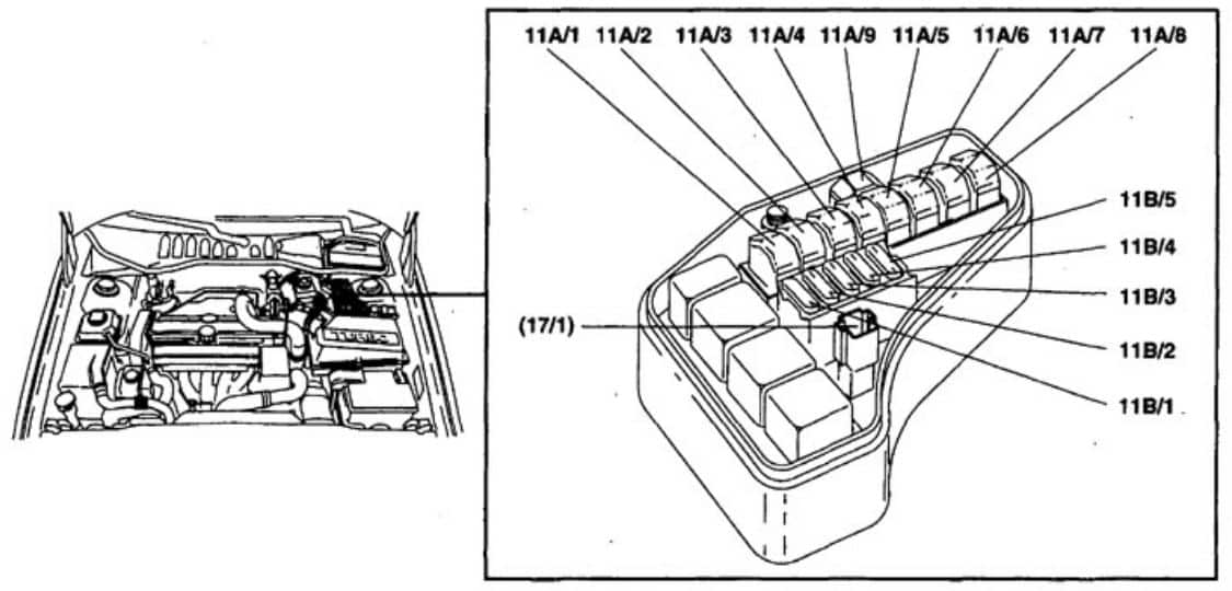
| Pozycja | Amperaż [A] | Chroniony obwód / funkcja |
|---|---|---|
| 1 | 60 | Engine cooling fan main high-current power feed |
| 2 | 50 | Main supply to the supplementary fuse carrier |
| 3 | 50 | Starter motor and secondary air pump |
| 4 | 50 | Anti-lock braking system (ABS) high-current supply |
| 5 | 50 | Main headlamp supply |
| 6 | 60 | Supply for supplementary fuse circuits |
| 7 | 60 | Additional supply for supplementary fuse circuits |
| 8 | 60 | Engine and automatic transmission controllers |
| 9 | – | Unoccupied in this 1998 North American handbook listing; certain diesel specifications have an 80 A glow-plug link at the corresponding high-current position |
| 10 | 10 | Ignition switch, ECM and automatic transmission controllers |
| 11 | 10 | Petrol fuel injectors |
| 12 | 20 | Fuel pump supply |
| 13 | 10 | Automatic transmission control unit |
| 14 | 10 | Air-conditioning relay |
| Some items listed are optional according to equipment, engine and market. The numbers above refer to the main relay/fuse block. | ||
Supplementary fuse box – positions 1-40
This carrier contains circuits for lighting, central locks, heater, stereo, rear wiper and the heated rear glass. Position 30 is deliberately shown as unoccupied in the North American Volvo 1998 owner’s handbook; a separate detailed Volvo S70/V70 service allocation lists 15 A for a front 12 V lighter at 11C/30. Do not infer which applies without checking the vehicle’s cover and installed harness.

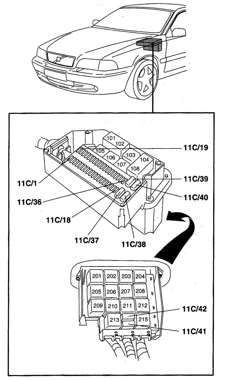
| Pozycja | Amperaż [A] | Chroniony obwód / funkcja |
|---|---|---|
| 1 | – | Unused location in the North American 1998 reference |
| 2 | 10 | Central door locking and automatic gearbox driving-mode selector |
| 3 | 10 | ABS control electronics |
| 4 | 10 | Immobiliser on Canadian-market cars |
| 5 | 15 | Climate system and OBD-II diagnostic connector |
| 6 | – | Unused in the 1998 North American handbook layout; some S70/V70 service configurations assign alarm equipment here |
| 7 | 15 | Radio / audio system |
| 8 | 15 | Canadian immobiliser, trip computer and headlamp switch |
| 9 | 20 | Electrically heated rear seat, on equipped cars |
| 10 | 15 | Ignition switch |
| 11 | 10 | Brake / stop lamps |
| 12 | – | Unused in this reference configuration; some markets have diesel heating or optional equipment |
| 13 | 15 | Hazard warning lamps, flash-to-pass headlights and remote central locking |
| 14 | 30 | Heated rear windscreen and exterior mirrors |
| 15 | 10 | Courtesy and glovebox lights, open-door lamps, luggage compartment illumination and belt reminder |
| 16 | 30 | Power antenna, trailer electrical socket and optional accessories |
| 17 | 20 | Front fog lamps |
| 18 | 10 | Key-in-ignition reminder |
| 19 | 15 | Left high-beam headlamp |
| 20 | 15 | Right high-beam headlamp and warning lamp |
| 21 | 15 | Left dipped-beam headlamp |
| 22 | 15 | Right dipped-beam headlamp |
| 23 | 10 | Left front and rear position lamps, left tail lamp and licence-plate lights |
| 24 | 10 | Right front and rear position lamps and right tail lamp |
| 25 | 10 | Rear fog lamp and indicator |
| 26 | 15 | Exterior lighting / headlamp switch |
| 27 | 15 | Reversing lamps and direction indicators |
| 28 | 25 | Heated front and/or rear seats, where fitted |
| 29 | 10 | Rear-window heater, shift interlock, belt reminder, cruise, heated mirrors and failed-bulb warning |
| 30 | – | Not assigned in the North American 1998 owner handbook; other S70/V70 11C/30 configurations list the front 12 V lighter at 15 A, so check the exact cover |
| 31 | 25 | Cabin ventilation fan and climate system |
| 32 | 10 | Audio system |
| 33 | 15 | Tailgate washer and wiper on the V70 estate |
| 34 | 25 | Front wipers, windscreen washers and horn |
| 35 | 10 | Instrument panel lighting, optional accessories and power sunroof |
| 36 | 15 | Rear 12 V auxiliary outlet and optional electric sunroof |
| 37 | Circuit breaker | Resetting circuit breaker for electric windows and sunroof, not a conventional blade fuse |
| 38 | – | Unused location |
| 39 | Circuit breaker | Resetting circuit breaker for driver’s electrically operated seat |
| 40 | Circuit breaker | Resetting circuit breaker for passenger’s electrically operated seat |
| Automatic circuit breakers (37, 39, 40) are resettable protections, not ordinary fuses. Exact equipment and circuit assignments can vary by market. | ||
Estate-specific, diesel and North American differences
The wagon’s rear-window wiper is supplied via supplementary fuse 33 (15 A), and the rear 12 V accessory socket is associated with fuse 36 (15 A) on equipped cars. Heated rear seats, powered sunroof and electric seats are optional. On diesel V70 models, glow plug and injection controls have additional functions that do not appear in the petrol-oriented US owner’s handbook; confirm the appropriate separate engine diagram.
The three automatic reset devices in positions 37, 39 and 40 are circuit breakers rather than normal fuses. If the seat or electric window is blocked, the 1998 owner handbook instructs the driver to remove the obstruction and allow the breaker to reset before testing again.
Fuel pump, wipers, rear-window heater and 12 V socket
Fuel pump: Main fuse 12 (20 A) covers the pump; injector supply is at main fuse 11 (10 A). Electrical diagnosis also requires checking pump relays and wiring if the fuses are intact.
Wipers: Supplementary fuse 33 (15 A) is for the rear tailgate wiper, while fuse 34 (25 A) covers front wipers/washer and horn. Heated rear window: Supplementary fuse 14 (30 A) also supplies heated exterior mirrors. Front cigarette lighter: Detailed service information lists 11C/30 as 15 A, but the 1998 North American handbook leaves position 30 blank; follow the fitted cover rather than guessing.
How this V70 relates to Volvo S70 and 850
See the Volvo S70 (1998-1999) guide for the detailed 11A/11B and 11C service-designation tables and the Volvo 850 (1993-1997) fuse box guide for the electrical system of the predecessor.
Technical reference: Volvo S70/V70 1998 Owner’s Manual, “Replacing fuses” and “Fuses”, pages 102-104, with separately labelled 1998 detailed electrical diagrams for comparison. Market, trim and powertrain differences take precedence.