
The Peugeot 106 second generation (1996-2003) uses three groups of fuses: a 16-position under-bonnet fuse box, a four-position high-current maxi-fuse carrier (MF1-MF4) and a 13-position fuse board below the dashboard on the driver’s side. The full tables here reproduce all 33 positions in the Peugeot 106 owner’s handbook revised 6 May 2002, including every unused slot. Earlier model years and different engines can have different ratings and circuits, so the 2002 chart must not automatically be applied to every 1996-2003 vehicle.
Where are the Peugeot 106 fuse boxes?
Under the bonnet: Turn the ignition off. Locate the battery by the left-hand wing, viewed in the normal forward driving direction. Beside the battery are a covered 16-fuse panel and a separate maxi-fuse block with four heavier links. Unhook the plastic covers carefully. These are physically distinct carriers, and MF1-MF4 are not a continuation of fuse positions 1-16.
Passenger compartment: Sit in the driver’s seat and look under the steering wheel at the lower dashboard. Press the lug on top of the small fuse access flap and pull the cover towards you. The board contains thirteen numbered positions. The layout is not a simple row of consecutive numbers; identify each position from the illustration rather than counting from one side.
Engine compartment fuse box – F1 to F16
The engine board controls the cooling fans, optional ABS, extra driving lamps, fuel pump, oxygen sensor, headlights and optional Pulsair air-injection system. Fuses 1, 7, 8 and 10 are unused in the 2002 factory chart. A diesel vehicle does not use all the same petrol injection and secondary air circuits.
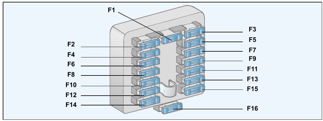
| Pozycja | Amperaż [A] | Chroniony obwód / funkcja |
|---|---|---|
| 1 | – | Unused socket in the 2002 handbook |
| 2 | 30 | Anti-lock braking system (ABS), first circuit where fitted |
| 3 | 25 | Engine cooling circuit |
| 4 | 20 | Anti-lock braking system (ABS), second circuit where fitted |
| 5 | 25 | Radiator cooling fan assembly |
| 6 | 20 | Additional driving lamps, if equipped |
| 7 | – | Unused socket in the 2002 handbook |
| 8 | – | Unused socket in the 2002 handbook |
| 9 | 10 | Fuel pump on corresponding petrol models |
| 10 | – | Unused socket in the 2002 handbook |
| 11 | 10 | Oxygen/lambda sensor on corresponding engine configuration |
| 12 | 10 | Left-hand main-beam headlamp |
| 13 | 10 | Right-hand main-beam headlamp |
| 14 | 10 | Left-hand dipped-beam headlamp |
| 15 | 10 | Right-hand dipped-beam headlamp |
| 16 | 30 | Pulsair secondary air-injection pump, if fitted |
High-current maxi-fuse block – MF1 to MF4
The physically separate maxi-fuse module has four vertically stacked links. The manufacturer’s illustration identifies them MF4 at the top, followed by MF3, MF2 and MF1 at the bottom. These protect the exterior lighting switch, ignition/start supply and power distribution to the cabin panel.
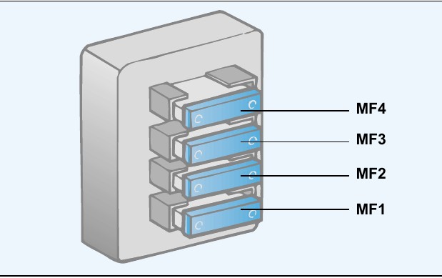
| Pozycja | Amperaż [A] | Chroniony obwód / funkcja |
|---|---|---|
| MF1 | 20 | Main supply to exterior lighting switch |
| MF2 | 80 | Ignition and starter positive feed during cranking |
| MF3 | 40 | Ignition-switched main supply after turning key |
| MF4 | 40 | Battery positive supply to the 13-fuse passenger-compartment panel |
Passenger-compartment fuse box – F1 to F13
The interior board powers the blower, rear-window heating, radio, horn, 12 V lighter, locks, lamps, mirrors, wipers and electric windows. The 2002 manual lists position 1 as unused, not a 5 A headlamp-levelling circuit; older wiring manuals describe alternative specifications, which should be matched by chassis number and market.
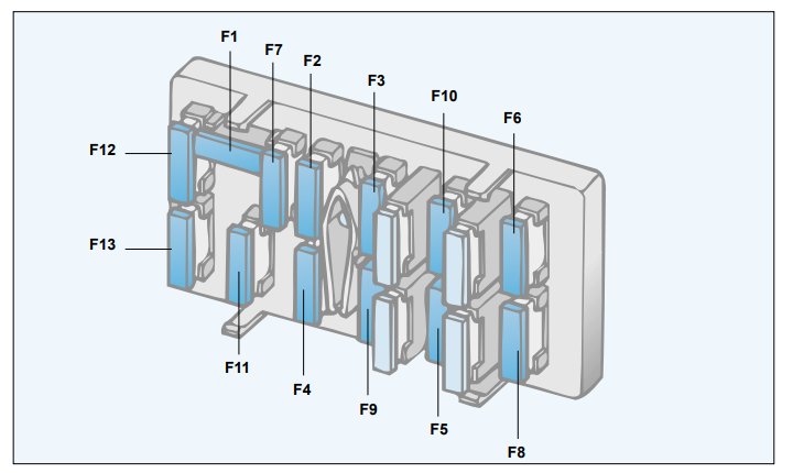
| Pozycja | Amperaż [A] | Chroniony obwód / funkcja |
|---|---|---|
| 1 | – | Unused location in the May 2002 handbook layout |
| 2 | 25 | Heater/ventilation blower motor |
| 3 | 25 | Heated rear window, air-conditioning, pressure switch and optional heated seats |
| 4 | 25 | Radio and map-reading lamp |
| 5 | 30 | Heated rear window, horn, cigarette lighter and heated exterior mirrors |
| 6 | 10 | Turn indicators and hazard warning flashers |
| 7 | 10 | Engine cooling control, electronic immobiliser, coolant temperature electronics, instrument cluster, power steering and reversing lights |
| 8 | 20 | Central door locking, immobiliser, passenger and boot lamps, coolant temperature control, instruments, radio and clock |
| 9 | 30 | Electric windows, warning lights, direction indicators, electric mirrors, brake lamps, front and rear windscreen wipers and instruments |
| 10 | 20 | Front electric window motors |
| 11 | 5 | Rear fog lamp and instrument cluster warning lights |
| 12 | 5 | Left rear position lamp, front position lamps, instrument panel dimmer and headlamp height correction |
| 13 | 5 | Switch lighting, radio controls, number-plate lamps and right rear position lamp |
1996-2000, 2001-2003 and petrol/diesel differences
The values here correspond to the specific 2002 Peugeot owner’s handbook. Older Peugeot 106 II wiring charts may assign different amperage or functions to ABS, electric windows, the heater blower, cooling fan and ignition/injection power supply. Some versions of the 1.0, 1.1, 1.4 and 1.6 petrol engines use a Pulsair pump and oxygen sensor, while 1.5 D diesel models have different engine management and heating equipment. Use the physical lid legend and original year/engine-specific documentation before changing a rating.
Blower fan, 12 V lighter, central locking and headlamps
Heater blower: Cabin fuse 2 (25 A) protects the fan; if only certain speeds fail, also examine the blower resistor or electronic speed controller. Cigarette lighter or horn: On this 2002 arrangement both are included in cabin fuse 5 (30 A), along with rear glass heating and heated mirrors.
Headlights: The left and right main beams use under-bonnet fuses 12 and 13 (10 A each), while the left and right dipped beams use fuses 14 and 15 (10 A each). Central locking, radio memory or clock: Check cabin fuse 8 (20 A) and inspect door wiring if the locks behave intermittently.
Engine cooling: Under-bonnet fuses 3 and 5 are rated 25 A each in the 2002 list. Check the appropriate cooling-fan relay, wiring and sensor if the fan still does not start.
Related Peugeot electrical diagrams
The older Peugeot 205 GTI / CTI uses a different 14-position arrangement, and the Peugeot 205 late 1995-1998 guide has its own assignments. The Peugeot 206 (2000-2002) succeeded the 106 era with a newer fuse-box architecture; none of these position numbers should be transferred between models.
Technical reference: Peugeot 106 Owner’s Handbook, “Practical Information”, pages 87-90, revision dated 06-05-2002; fuse positions, amperages and empty locations checked against the official tables.