
The first-generation Toyota C-HR (2017, AX10/AX50) was sold in Europe with a 1.2-litre turbocharged petrol engine and a 1.8 Hybrid (ZYX10, 2ZR-FXE) powertrain. Their main fuseboxes do not have identical positions: the petrol and hybrid engines need to be identified before selecting a fuse or following an under-bonnet diagram.
This technical reference retains 189 fuse and relay positions in five full tables: 37 cabin fuses, 79 positions in the 1.2 Turbo engine compartment, 63 positions in the 1.8 Hybrid engine box, six positions in an additional hybrid controller module and four main high-current fusible links. All spares, uncertain positions, relays, and equipment-dependent ratings are retained rather than silently omitted.
Front cigarette lighter / 12 V power outlet: cabin position 36, P/OUTLET NO.1 (15 A). The same basic European cabin listing is shown for both early petrol and hybrid C-HRs, but the main under-bonnet fuse numbering differs substantially between them.
Where are the Toyota C-HR 2017 fuse boxes?
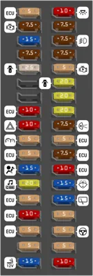
Inside the cabin: in a left-hand-drive European C-HR, the fuse holder is under the driver’s dashboard around the lower steering-column/footwell trim. Turn off the ignition, move the seat back and gently release the fuse cover. Read the numbers on its underside and match them to the cabin layout shown below. The right-hand-drive version uses a different access arrangement at the opposite side of the dashboard, so use the right-hand-drive illustration in the specific owner’s manual.
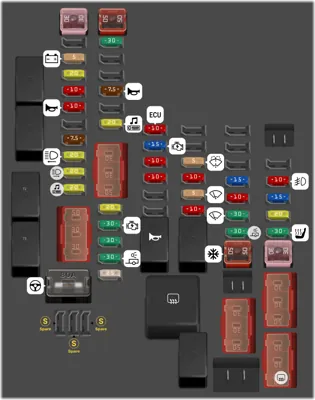
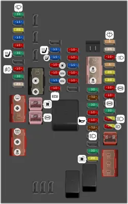
Engine compartment: with the car switched fully off, lift the bonnet and locate the large plastic fuse and relay carrier toward the front of the engine bay, near the 12 V battery connections. Squeeze the lid latches, lift the cover and read its embossed fuse legend. Refit the cover carefully to prevent water ingress. There are different layouts for the 1.2 Turbo and 1.8 Hybrid.
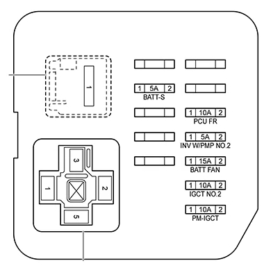
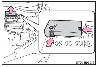
Hybrid auxiliary module: some ZYX10 vehicles have an additional small protected 12 V control module at the other side of the engine bay for hybrid power management and related pumps. This is not an invitation to open the high-voltage traction battery or inverter. Orange high-voltage cables and drive components require qualified hybrid service procedures.
Cabin fusebox – all positions 1-37
The 37-position cabin panel protects ignition-switched electronics, body control, door locking and windows, SRS airbags, interior lighting, washer and rear wiper, power steering control and the 12 V socket. Cabin 11 and 13 are vacant in the particular European diagram, while 22 requires a fitment check rather than an invented rating.
The usual first checks include 27 WASHER (15 A) for the washer pump, 29 WIPER RR (15 A) for the rear wiper and 36 P/OUTLET NO.1 (15 A) for the front accessory socket.
| Position | Amperage [A] | Protected circuit / function |
|---|---|---|
| 1 | 5 | ECU-B NO.1: permanent supply for selected engine and body electronics controllers |
| 2 | 10 | DOME: interior cabin, courtesy and access-system lighting |
| 3 | 7.5 | AM2: starter and immobiliser electronic supply |
| 4 | 7.5 | DOOR BACK: tailgate lock and release control |
| 5 | 15 | STRG LOCK: electronic steering-column lock |
| 6 | 7.5 | FOG RR: rear fog lamp circuit |
| 7 | 7.5 | STOP: brake lights and brake signal used by safety systems |
| 8 | 7.5 | OBD: on-board diagnostic connector |
| 9 | 25 | D/L: central door locking and unlocking |
| 10 | 5 | AM1: starting-system supply |
| 11 | – | Unused socket in this specified 2017 European configuration |
| 12 | 20 | DOOR: main door controller and electric window supply |
| 13 | – | Unused socket in this specified 2017 European configuration |
| 14 | 20 | DOOR R/R: right rear door power window motor |
| 15 | 10 | ECU-B NO.2: supplementary body electronics power |
| 16 | 20 | DOOR R/L: left rear door power window motor |
| 17 | 10 | HAZ: hazard warning lamps |
| 18 | 7.5 | BKUP LP: reversing lamps and selected audio/rear-view equipment |
| 19 | 5 | METER-IG2: instrument cluster supply |
| 20 | 5 | ECU-IG1 NO.1: drive system and driver assistance controllers |
| 21 | 5 | ECU-IG2 NO.3: ignition-switched powertrain and safety electronics |
| 22 | – | Unconfirmed socket in this European 2017 table; match fusebox lid and VIN |
| 23 | 7.5 | ECU-IG1 NO.3: ignition-switched vehicle electronics |
| 24 | 15 | A/BAG-IG2: supplemental restraint system SRS / airbag ECU |
| 25 | 10 | ECU-IG1 NO.4: vehicle, lighting and comfort equipment controllers |
| 26 | 20 | RADIO: infotainment, radio and audio amplifier |
| 27 | 15 | WASHER: windscreen washer fluid pump |
| 28 | 5 | ECU-DCC NO.1: ECU power cutoff and control |
| 29 | 15 | WIPER RR: rear windscreen wiper |
| 30 | 10 | ECU-DCC NO.2: additional electronics supply circuit |
| 31 | 5 | ECU-IG1 NO.2: ignition-switched controller supply |
| 32 | 5 | ECU-ACC: accessory electronics supply |
| 33 | 5 | EPS-IG1: electric power steering controller |
| 34 | 5 | SFT LOCK-ACC: automatic transmission gear selector shift lock |
| 35 | 5 | PANEL: dashboard and console illumination |
| 36 | 15 | P/OUTLET NO.1: front 12 V accessory socket / cigarette lighter |
| 37 | 10 | TAIL: side, tail and marker lights and dashboard lighting |
1.2 Turbo – complete 79-position engine fuse and relay box
The 1.2 Turbo layout provides EFI engine-management protection, starting and charging circuits, ABS, cooling, petrol ignition, headlights, Stop & Start, optional towing and electrical heater power. All 79 numbered locations are included, even where the manufacturer’s European list identifies the socket as SPARE or reserves a relay location.
In this petrol arrangement 8 H-LP LH (20 A) supplies the left headlight and 9 H-LP RH (20 A) the right, while 31 MIR HTR (10 A) powers heated mirrors and 39 WIPER (30 A) front wipers. High-current links and relay positions are listed separately within the same numbered drawing; do not substitute a normal blade fuse for a relay.
| Position | Amperage [A] | Protected circuit / function |
|---|---|---|
| 1 | – | SPARE: spare fuse storage location in the 2017 European listing, not a protected consumer |
| 2 | 5 | BATT-S: battery condition and Stop & Start / charging monitor |
| 3 | 20 | D INJ: petrol engine fuel injection controls |
| 4 | 10 | ETCS: electronic throttle control system |
| 5 | 10 | HORN: horn circuit |
| 6 | – | SPARE: spare fuse storage location in the 2017 European listing, not a protected consumer |
| 7 | 7.5 | DCM/MAYDAY: emergency communication/telematics module if fitted |
| 8 | 20 | H-LP LH: left front headlamp, equipment dependent |
| 9 | 20 | H-LP RH: right front headlamp, equipment dependent |
| 10 | 20 | AMP NO.1: factory audio amplifier circuit 1 |
| 11 | 30 | D/C CUT: controlled accessory power disconnection |
| 12 | – | SPARE: spare fuse storage location in the 2017 European listing, not a protected consumer |
| 13 | – | SPARE: spare fuse storage location in the 2017 European listing, not a protected consumer |
| 14 | 7.5 | S-HORN: factory security siren |
| 15 | – | SPARE: spare fuse storage location in the 2017 European listing, not a protected consumer |
| 16 | 20 | AMP NO.2: factory audio amplifier circuit 2 |
| 17 | 20 | EFI-MAIN NO.1: primary engine fuel injection power |
| 18 | 30 | ST: starter motor control circuit |
| 19 | 30 | EFI-MAIN NO.2: secondary injection system main feed |
| 20 | 30 | TOWING-B: towing and trailer power circuit, where fitted |
| 21 | 25 | IG2-MAIN: main ignition power rail |
| 22 | 10 | ECU-IG2 NO.1: powertrain controller supply |
| 23 | 15 | IGN: petrol ignition power circuit |
| 24 | 10 | EFI NO.2: fuel injection control electronics |
| 25 | 10 | EFI NO.3: auxiliary engine management control |
| 26 | – | SPARE: spare fuse storage location in the 2017 European listing, not a protected consumer |
| 27 | – | SPARE: spare fuse storage location in the 2017 European listing, not a protected consumer |
| 28 | – | SPARE: spare fuse storage location in the 2017 European listing, not a protected consumer |
| 29 | – | SPARE: spare fuse storage location in the 2017 European listing, not a protected consumer |
| 30 | 5 | WASHER-S: washer system control signal |
| 31 | 10 | MIR HTR: heated exterior mirrors |
| 32 | 5 | WIPER-S: windscreen wiper control feed |
| 33 | 10 | EFI NO.4: engine ECU additional supply |
| 34 | – | SPARE: spare fuse storage location in the 2017 European listing, not a protected consumer |
| 35 | – | SPARE: spare fuse storage location in the 2017 European listing, not a protected consumer |
| 36 | – | SPARE: spare fuse storage location in the 2017 European listing, not a protected consumer |
| 37 | 15 | STRG HTR: heated steering wheel, if equipped |
| 38 | 10 | FUEL OPN: electric fuel filler flap release |
| 39 | 30 | WIPER: front windscreen wiper motor |
| 40 | 30 | TOWING-ALT: alternative trailer power feed |
| 41 | – | SPARE: spare fuse storage location in the 2017 European listing, not a protected consumer |
| 42 | 10 | FOG FR: front fog lamps |
| 43 | 15 | DEICER: windscreen wiper de-icer heater |
| 44 | 20 | DOOR DBL/L: double-locking door system |
| 45 | 30 | S/HTR-MAIN: main heated seat power |
| 46 | – | DEF RELAY: rear window heater relay location, not a fuse |
| 47 | 50 | J/B-B: body junction block main power supply |
| 48 | 30 | H-LP CLN: headlamp washer pump |
| 49 | – | SPARE: spare fuse storage location in the 2017 European listing, not a protected consumer |
| 50 | 30 | BBC NO.2: Stop & Start battery/boost supply circuit |
| 51 | 30 | BBC NO.1: additional Stop & Start control circuit |
| 52 | – | SPARE: spare fuse storage location in the 2017 European listing, not a protected consumer |
| 53 | – | SPARE: spare fuse storage location in the 2017 European listing, not a protected consumer |
| 54 | – | SPARE: spare fuse storage location in the 2017 European listing, not a protected consumer |
| 55 | – | SPARE: spare fuse storage location in the 2017 European listing, not a protected consumer |
| 56 | 30 | PTC HTR NO.2: auxiliary electric cabin heater stage 2 |
| 57 | 30 | FAN NO.2: cooling fan circuit 2 |
| 58 | 50 | PTC HTR NO.1: auxiliary electric cabin heater stage 1 |
| 59 | 30 | FAN NO.1: cooling fan circuit 1 |
| 60 | – | SPARE: spare fuse storage location in the 2017 European listing, not a protected consumer |
| 61 | 50 | DEF: heated rear window and side mirrors |
| 62 | 30 | ABS-MAIN: main ABS/ESP hydraulic system supply |
| 63 | 50 | ABS MTR NO.1: ABS pump motor power |
| 64 | 80 | EPS: electric power steering high-current feed |
| 65 | 50 | HTR: air-conditioning and cabin ventilation blower |
| 66 | – | SPARE: spare fuse storage location in the 2017 European listing, not a protected consumer |
| 67 | 30 | PTC HTR NO.3: electric auxiliary heater stage 3 |
| 68 | – | SPARE: spare fuse storage location in the 2017 European listing, not a protected consumer |
| 69 | – | SPARE: spare fuse storage location in the 2017 European listing, not a protected consumer |
| 70 | – | Unassigned relay position in the 2017 European reference, not a blade fuse |
| 71 | – | Unassigned relay position in the 2017 European reference, not a blade fuse |
| 72 | – | EFI-MAIN NO.2 RELAY: fuel injection main relay |
| 73 | – | D INJ RELAY: engine fuel injection relay |
| 74 | – | HORN RELAY: horn control relay |
| 75 | – | Unassigned relay position in the 2017 European reference, not a blade fuse |
| 76 | – | Unassigned relay position in the 2017 European reference, not a blade fuse |
| 77 | – | SPARE: replacement fuse held in reserve, not an actively supplied consumer |
| 78 | – | SPARE: replacement fuse held in reserve, not an actively supplied consumer |
| 79 | – | SPARE: replacement fuse held in reserve, not an actively supplied consumer |
1.8 Hybrid ZYX10 – complete 63-position engine fusebox
Hybrid 1.8 uses a different engine power distribution carrier. It includes 31 BATT FAN (15 A) for the traction-battery cooling fan controller, 29 PM-IGCT (10 A) for hybrid management, 32 PCU FR (10 A) for power control electronics and 33 INV W/PMP (10 A) for inverter coolant pump control. These are 12 V controls serving the hybrid powertrain, not the traction battery’s high-voltage service protection.
Positions 59 and 60 protect right and left headlights with 10 A or 20 A depending on the type of headlamp. Other specified fuses carry See cover where the original European listing did not give a universally applicable amp rating. The 1.2 Turbo fuse locations must not be copied into this hybrid box.
| Position | Amperage [A] | Protected circuit / function |
|---|---|---|
| 1 | 30 | WIPER: front windscreen wiper motor |
| 2 | 15 | STRG HTR: heated steering wheel, where fitted |
| 3 | 20 | DOOR DBL/L: electric door double-lock circuit |
| 4 | 15 | DEICER: front wiper / windscreen heating |
| 5 | 10 | FUEL OPN: electric fuel filler flap release |
| 6 | 30 | S/HTR-MAIN: heated seat main supply |
| 7 | – | No universal circuit assigned in this 2017 hybrid reference; check the fitted lid and VIN before using this socket |
| 8 | 10 | FOG FR: front fog lamp supply |
| 9 | 30 | TOWING-DC/DC: optional trailer electrical circuit and DC/DC supply |
| 10 | 25 | ENG W/PMP: electric internal combustion engine water pump |
| 11 | See cover | DEF: heated rear glass and door mirrors; rating depends on actual fuse cover |
| 12 | See cover | PTC HTR NO.3: auxiliary electric cabin heater stage 3; verify rating |
| 13 | – | No universal circuit assigned in this 2017 hybrid reference; check the fitted lid and VIN before using this socket |
| 14 | See cover | HTR: HVAC blower and cabin heating power; verify rating |
| 15 | See cover | PTC HTR NO.2: auxiliary cabin electric heater stage 2; verify rating |
| 16 | See cover | ABS MTR NO.2: ABS pump motor circuit 2; verify rating |
| 17 | – | No universal circuit assigned in this 2017 hybrid reference; check the fitted lid and VIN before using this socket |
| 18 | See cover | FAN NO.2: engine cooling fan circuit 2; verify rating |
| 19 | See cover | PTC HTR NO.1: auxiliary cabin heater stage 1; verify rating |
| 20 | 30 | FAN NO.1: engine cooling fan circuit 1 |
| 21 | 30 | ABS-MAIN: main ABS/ESP controller feed |
| 22 | – | No universal circuit assigned in this 2017 hybrid reference; check the fitted lid and VIN before using this socket |
| 23 | 15 | S/HTR F/L: driver-side heated front seat |
| 24 | 15 | S/HTR F/R: passenger-side heated front seat |
| 25 | 10 | EFI NO.2: engine management and cooling circuits |
| 26 | 10 | EFI NO.3: internal-combustion engine ECU |
| 27 | 15 | INJ: fuel injection and ignition supply |
| 28 | 10 | ECU-IG2 NO.1: hybrid controller, cruise and active safety functions |
| 29 | 10 | PM-IGCT: main hybrid power management control |
| 30 | 10 | IGCT NO.2: hybrid system and security electronics feed |
| 31 | 15 | BATT FAN: high-voltage battery cooling fan controller, 12 V protection |
| 32 | 10 | PCU FR: power control unit electronics of hybrid drive |
| 33 | 10 | INV W/PMP: inverter coolant pump control, 12 V protected supply |
| 34 | – | No universal circuit assigned in this 2017 hybrid reference; check the fitted lid and VIN before using this socket |
| 35 | – | No universal circuit assigned in this 2017 hybrid reference; check the fitted lid and VIN before using this socket |
| 36 | See cover | IGCT-IG: hybrid drive ECU ignition-switched supply; verify rating |
| 37 | See cover | ABS MTR NO.3: ABS motor circuit 3; verify rating |
| 38 | See cover | ABS MTR NO.1: ABS motor circuit 1; verify rating |
| 39 | 30 | TOWING-B: factory tow equipment electrical supply |
| 40 | 7.5 | S-HORN: vehicle security alarm siren |
| 41 | 30 | EPB NO.2: electric parking brake supply 2 |
| 42 | 10 | ETCS: electronic throttle control |
| 43 | 10 | HORN: horn |
| 44 | 7.5 | H-LP SHADE: headlamp shutter and levelling control |
| 45 | – | No universal circuit assigned in this 2017 hybrid reference; check the fitted lid and VIN before using this socket |
| 46 | – | No universal circuit assigned in this 2017 hybrid reference; check the fitted lid and VIN before using this socket |
| 47 | 30 | D/C CUT: accessory power cut-off control |
| 48 | 20 | EFI-MAIN: main petrol engine ECU supply in the hybrid |
| 49 | 5 | WASHER-S: windscreen and optional headlamp washer controls |
| 50 | 25 | IG2-MAIN: hybrid and vehicle ignition power |
| 51 | 10 | DRL: daytime running lamps |
| 52 | 5 | BATT-S: hybrid battery/charging status monitoring |
| 53 | 20 | AMP NO.1: factory audio amplifier circuit 1 |
| 54 | 20 | AMP NO.2: factory audio amplifier circuit 2 |
| 55 | 10 | ABS NO.3: ABS controller auxiliary supply |
| 56 | 10 | ABS NO.2: ABS controller auxiliary supply |
| 57 | – | No universal circuit assigned in this 2017 hybrid reference; check the fitted lid and VIN before using this socket |
| 58 | 30 | EPB NO.1: electronic parking brake supply 1 |
| 59 | 10 / 20 | H-LP RH: right front headlamp, 10 or 20 A depending on lamp unit |
| 60 | 10 / 20 | H-LP LH: left front headlamp, 10 or 20 A depending on lamp unit |
| 61 | 50 | J/B-B: main body electronics junction supply |
| 62 | – | No universal circuit assigned in this 2017 hybrid reference; check the fitted lid and VIN before using this socket |
| 63 | See cover | H-LP CLN: headlight washer pump, where fitted; verify rating |
Additional six-position hybrid fuse module
The additional protected controller group on equipped hybrid C-HRs contains BATT FAN (15 A), BATT-S (5 A), IGCT NO.2 (10 A), INV W/PMP NO.2 (5 A), PCU FR (10 A) and PM-IGCT (10 A). The same circuit name can occur in more than one fusebox in different variants, so always identify which physical carrier and drawing is installed.
| Position | Amperage [A] | Protected circuit / function |
|---|---|---|
| 1 | 15 | BATT FAN: traction battery cooling blower 12 V controller power |
| 2 | 5 | BATT-S: hybrid battery monitoring and vehicle charge management |
| 3 | 10 | IGCT NO.2: hybrid drive ignition-switched controller circuit |
| 4 | 5 | INV W/PMP NO.2: second inverter coolant pump circuit |
| 5 | 10 | PCU FR: power control unit electronics of hybrid drive |
| 6 | 10 | PM-IGCT: hybrid main power management circuit |
Four main high-current battery protection links
The original reference also lists BATT/MAIN (140 A), DC/DC (120 A), EPS (80 A) and J/B-AM (60 A). These high-current links are not the same as miniature blade fuses. Their precise presence and ratings depend on the installed hybrid or 12 V electrical distribution assembly. Workshop-level isolation and the correct Toyota service guide are necessary before replacing a high-current link.
| Position | Amperage [A] | Protected circuit / function |
|---|---|---|
| 1 | 140 | BATT / MAIN: 140 A primary vehicle 12 V power distribution link on the documented configuration |
| 2 | 120 | DC/DC: 120 A main feed for hybrid DC/DC converter 12 V output |
| 3 | 80 | EPS: 80 A electric power steering main protected supply |
| 4 | 60 | J/B-AM: 60 A junction box, lighting and passenger-compartment main power |
2017 European 1.2 Turbo versus 1.8 Hybrid
The petrol 1.2 Turbo uses a conventional petrol engine starter, fuel injection and Stop & Start support, while the ZYX10 1.8 Hybrid adds DC/DC power conversion, hybrid motor controllers, separate inverter cooling and traction battery ventilation. Fuse functions such as BATT FAN, IGCT, PCU FR and INV W/PMP therefore have no direct 1:1 equivalent in the petrol engine chart.
European 2017 model-year data should not be applied without checks to North American versions, later 2018/2019 revisions or the 2.0-litre hybrid added with the 2019 facelift. Market variations in headlamp type, factory towbar, seat heaters and audio also change the populated positions. Check the fusebox cover and the correct Toyota handbook for the VIN.
Toyota C-HR electrical fault diagnosis
Front 12 V outlet does not work: inspect cabin 36 (15 A). Remove chargers, check the socket centre contact and replace only with the original rating.
Rear wiper fails: check cabin 29 (15 A) and the motor or tailgate loom. If the washer pump does not operate, check cabin 27 (15 A) and the pump electrical connection.
Petrol C-HR headlight or mirror heater fault: the 1.2 Turbo main box uses 8 and 9 (20 A) for the left and right headlights, and 31 (10 A) for mirror heating. In a hybrid, headlight positions are 59 and 60 (10/20 A); determine the installed lamp type before replacement.
Hybrid system will not enter READY: first diagnose the 12 V battery and read hybrid-control fault codes. The PCU FR, BATT-S, IGCT and DC/DC circuits must not be bypassed or replaced based on the 1.2 Turbo chart. Never touch orange high-voltage wires.
Repeated fuse failure: if a replacement of the correct specification blows again, inspect for shorted wiring or a faulty load rather than installing a fuse with greater current capacity.
Other Toyota fuse diagrams
The Toyota Auris I E150 (2006-2012) provides a guide to an earlier Toyota compact vehicle. The later Toyota Corolla Cross Hybrid (2020-on) uses a more recent hybrid architecture with its own fuse allocations; neither should be substituted for a 2017 C-HR.
Manufacturer references: Toyota C-HR 2017 European owner’s manual, C-HR Hybrid 2017 European owner’s manual (2ZR-FXE), and Toyota C-HR 2016 European rescue card for location context. The existing diagrams from the Polish article have been preserved.