
Toyota Echo (1999-2005) is a compact model closely related to the Toyota Yaris I and Vitz XP10. North American Echo sedans were commonly fitted with the 1.5-litre 1NZ-FE petrol engine, while other markets offered different body styles and electrical equipment. This guide preserves every entry and relay from the original three tables, and distinguishes earlier XP10 wiring diagrams from the Toyota Echo 2005 US owner’s manual.
The car can have a passenger compartment fuse panel, a main fuse and relay box under the bonnet, an optional auxiliary headlight / daytime running lights (DRL) box and a separate high-current fusible-link block. The names FL1-FL4 in the table are used only to identify the separate MAIN/ALT/ABS high-current carrier, not positions printed in the primary engine fuse box.
Cigarette lighter and 12 V accessory supply: check ACC (15 A) in the cabin fuse panel. Some versions also have P/POINT (15 A) for an accessory socket, but the US Echo 2005 manual assigns no consumer to P/POINT. Compare your fitted carrier before using that second label.
Where are the Toyota Echo fuse boxes?
Cabin panel: in a left-hand-drive Echo, look below the driver’s side of the dashboard. Move the driver’s seat back, turn off the ignition, release the small fuse-cover panel and check the label on its reverse. In a right-hand-drive vehicle, the access layout and adjacent modules can differ. Depending on equipment, small relays for lighting, door locking and the heater are installed near the fuse carrier.
Engine box: open the bonnet with the engine and ignition switched off. Find the covered fuse box near the battery and side of the engine compartment, release its clips and compare the printed numbers with the engine diagram. Some markets also have a separate DRL/headlight box and additional bolted fusible links along the battery’s main power feed. Do not disconnect or bypass a high-current link while the battery is live.
Main engine compartment – fuses 1-17, FL1-FL4 and relays R1-R9
The illustrated primary engine carrier has positions 1-17 with relays R1-R9. It protects the EFI injection system, horn, starter, engine control, radiator fans, optional PTC heater and some headlight circuits. Positions 10-12 are holders for spare fuses and do not power any consumer, while 6, 13, 14 and 17 are unoccupied in this version.
The four FL1-FL4 entries refer to an additional high-current block. FL1 (60 A) is the MAIN link, FL3 is the ALT link and may be 100 or 120 A according to the vehicle and handbook, and FL4 (60 A) supplies ABS where fitted. FL2 is unused. The schematic immediately below illustrates the main fuse box, not necessarily the separate FL1-FL4 carrier.
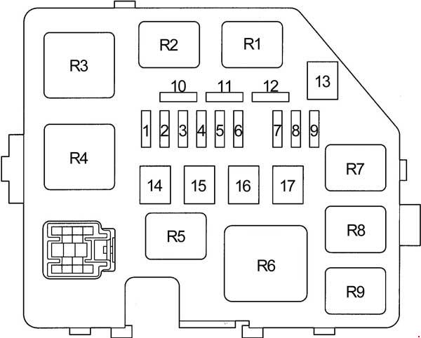
| Position | Amperage [A] | Protected circuit / function |
|---|---|---|
| 1 | 15 | DOME: clock, cabin lamps, instrument panel, radio memory and central locking on equipped cars |
| 2 | 15 | EFI: fuel injection and engine control, immobiliser and ECT automatic transmission controls |
| 3 | 15 | HORN: horn |
| 4 | 15 | AM2: ignition switch, starting, engine ECU, charging system and SRS airbag supply |
| 5 | 30 | ST: starter circuit and starter relay |
| 6 | – | Unoccupied in this layout |
| 7 | 10 | H-LP LH / H-LP LO LH: left headlight and levelling, with exact name and DRL varying by market |
| 8 | 10 | H-LP RH / H-LP LO RH: right headlight and levelling, with name and DRL varying by market |
| 9 | 15 | P/POINT: accessory socket on equipped cars; listed without an assigned circuit in the US 2005 Echo sedan handbook |
| 10 | – | Spare fuse holder, not a protected circuit |
| 11 | – | Spare fuse holder, not a protected circuit |
| 12 | – | Spare fuse holder, not a protected circuit |
| 13 | – | No assigned circuit |
| 14 | – | Unoccupied in this layout |
| 15 | 30 | RDI: radiator and A/C condenser cooling fans |
| 16 | 50 | HTR SUB1: auxiliary PTC electric heater on equipped cars |
| 17 | – | Unoccupied in this layout |
| FL1 | 60 | FL1 MAIN: separate high-current box position 1, main supply for EFI, DOME, HORN, ST, AM2 and headlamps |
| FL2 | – | FL2: unused position in the separate high-current block |
| FL3 | 100 / 120 | FL3 ALT: alternator and main electrical supply, 100 or 120 A in the US 2005 handbook; other XP10 listings specify 120 A |
| FL4 | 60 | FL4 ABS: main ABS supply if the vehicle is equipped with ABS |
| R1 | – | Radiator cooling fan relay |
| R2 | – | Radiator cooling fan relay |
| R3 | – | Starter relay |
| R4 | – | Unused relay position |
| R5 | – | Accessory power socket relay |
| R6 | – | Additional PTC heater relay |
| R7 | – | Fuel injection power relay |
| R8 | – | A/C compressor clutch relay |
| R9 | – | Horn relay |
Supplementary headlamp / daytime running light fuse carrier
Some factory DRL systems have two separate 10 A main-beam fuses, one for each side, and headlight relays including DIM for dipped/main beam selection. Vehicles without factory DRL can have unoccupied sockets. Do not use this supplemental box as a substitute for the main panel on an Echo with different regional headlight wiring.
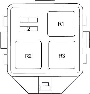
| Position | Amperage [A] | Protected circuit / function |
|---|---|---|
| 1 | 10 | H-LP HI RH: right main-beam headlamp in vehicles equipped with factory daytime running lights |
| 2 | 10 | H-LP HI LH: left main-beam headlamp and cluster indication on DRL-equipped vehicles |
| R1 | – | Headlight relay |
| R2 | – | DIM: dipped-beam / main-beam switching relay |
| R3 | – | Unused relay position |
Passenger compartment fuse panel – all positions and variants
The cabin fuse diagram covers positions 1-20, two named DEF entries, alternative current ratings and four relays. It includes radio, accessory outlet, wipers, central locking, brake lights, heated rear window, power windows and cabin blower. Repeated printed positions in the table describe different layouts, not two fuses occupying the same socket.
For the 2005 US Echo sedan, Toyota specifies TAIL (10 A) rather than the earlier regional 7.5 A version and AM1 (40 A) instead of 50 A in some older XP10 listings. Both alternatives are preserved to avoid misleading owners of imported cars.
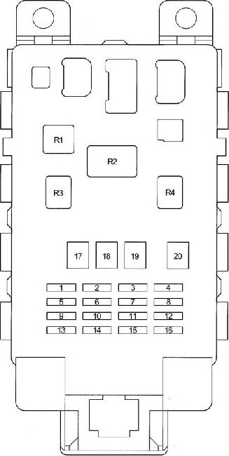
| Position | Amperage [A] | Protected circuit / function |
|---|---|---|
| 1 | 10 | GAUGE: cluster, reversing lamps, charging system, climate control, engine, locks and selected comfort equipment |
| 2 | 10 | DEF RLY: heated rear window relay control and optional heated mirrors |
| 2 | 20 | DEF: heated rear window and optional mirrors; a separate diagram version uses this label elsewhere as well |
| 3 | 25 | D/L: power door locks, double locking and remote controls on equipped versions |
| 4 | 7.5 | TAIL: side lamps, tail lamps, licence plate lamps and switch backlighting, older XP10 7.5 A configuration |
| 4 | 10 | TAIL: US 2005 Echo edition 10 A alternative |
| 5 | – | Unoccupied in the illustrated version |
| 6 | 20 | WIPER: windscreen wipers and washer, plus rear wiper on some related hatchback models, but not on Echo sedan |
| 7 | 7.5 | ECU-B: body electronics and SRS supply depending on specification |
| 8 | 15 | FOG: front fog lights |
| 9 | 15 | ACC: cigarette lighter and 12 V outlet, clock, radio, power mirrors and other ignition accessory circuits |
| 10 | 7.5 | ECU-IG: ignition-switched ECU supply for ABS, SRS, cooling and auxiliary heating |
| 11 | 7.5 | OBD: diagnostic connector |
| 12 | 10 | HAZ: direction indicators and hazard warning lamps |
| 13 | 7.5 | A.C: climate control and cabin heater electronics |
| 14 | 10 | S-HTR: heated front seats if equipped |
| 15 | – | Unoccupied in the illustrated version |
| 16 | 10 | STOP: brake lamps and brake signal to engine and automatic transmission controllers, including shift-lock |
| 17 | 50 | AM1: main feed for ACC, GAUGE, WIPER and ECU-IG, 50 A in older XP10 diagram |
| 17 | 40 | AM1: US 2005 Echo sedan 40 A alternative |
| 18 | 30 | POWER: electric windows and optional sunroof |
| 19 | 40 | HTR: cabin heating, blower and A/C supply |
| 20 | 30 | DEF: heated rear window and optional heated mirrors; separate listed DEF position |
| R1 | – | Cabin heater relay |
| R2 | – | Lighting relay |
| R3 | – | Electric windows relay |
| R4 | – | C/OPN fuel pump opening relay |
Different engines, markets and model years
The US 2005 Echo sedan owner’s manual has 31 fuse listings across several boxes and fuse types A, B and C. Its manual numbers are not interchangeable with the 1-17 numbers printed in an older XP10 engine-box drawing. The manual also lists EFI 15 A, DOME 15 A, WIPER 20 A, ACC 15 A, OBD 7.5 A, STOP 10 A, MAIN 60 A and ABS 60 A. Use the vehicle’s actual identification, the fuse-carrier lid and its matching owner’s manual when there is a discrepancy.
The three- and five-door Yaris/Vitz variants can have a rear wiper while a typical North American Echo sedan does not. Do not diagnose a sedan using a hatchback’s rear-wiper position. The second-generation Yaris XP90 introduced another electrical architecture from 2005 in some markets.
Toyota Echo electrical troubleshooting
Radio or 12 V socket is dead: inspect cabin ACC (15 A). The separate P/POINT (15 A) function depends on market and model; in the 2005 US handbook it is shown without a protected consumer. Inspect the socket and any phone charger for shorts.
Front wipers stop: check cabin WIPER (20 A), then the ignition feed, wiper switch and motor linkage. An Echo sedan does not have the rear wiper used in some related Yaris hatchbacks.
Engine will not crank: inspect engine ST (30 A), AM2 (15 A) and EFI (15 A) where they match the fitted box. Check the starter relay and battery condition, and diagnose repeated fuse failures rather than increasing the amperage.
Heated rear glass fails: confirm the correct DEF fuse and DEF RLY control. The regional tables include more than one DEF-labelled position, so verify which one is populated in the car.
Related Toyota models
The most closely related model is the Toyota Yaris I XP10 (1999-2005), whose hatchbacks can have different rear electrical equipment. The newer Yaris II XP90 (2005-2012) uses a different set of fuse carriers despite overlap in the model years.
Factory reference: Toyota Echo 2005 sedan owner’s handbook, fuse protection chapter, compared with older regional Echo/Yaris XP10 fuse and relay drawings. Use VIN-specific owner and repair documentation for other markets.