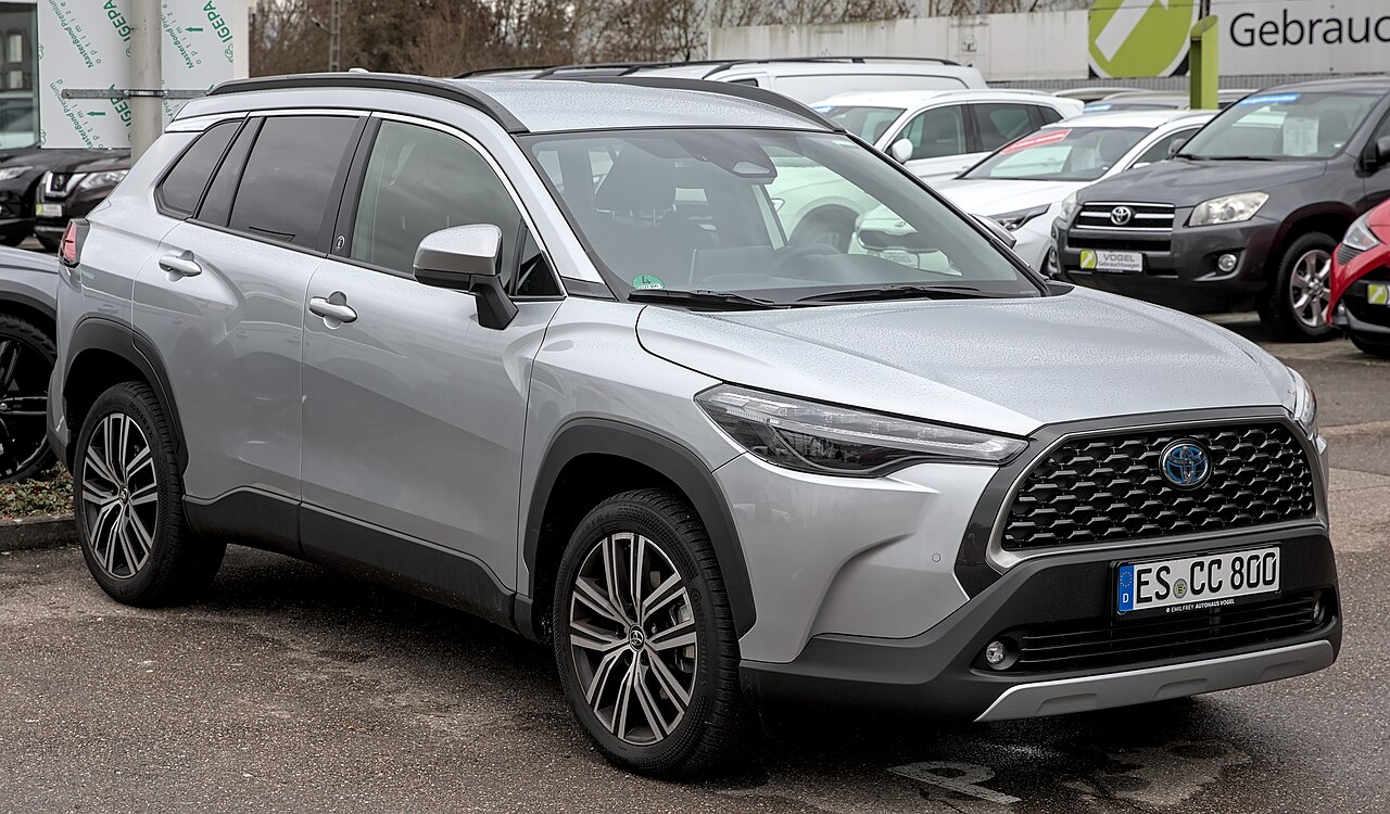
The Toyota Corolla Cross XG10 entered production in 2020 and reached European markets in 2022. It has fuse and relay boxes in the engine compartment and under the dashboard. The detailed tables here cover selected 2024 European hybrid configurations, including the 1.8-litre 2ZR-FXE and 2.0-litre M20A-FXS, with separate production-layout variants.
Important compatibility note: fuse positions, equipment, ratings and even the physical arrangement of the fuse boxes can differ between engine types, model years, assembly plants and markets. The TMC and alternative 2ZR layouts below are not interchangeable. Always inspect the fuse label, position and original rating on your own vehicle first.
Where are the Toyota Corolla Cross fuse boxes?
Engine compartment: the fuse/relay assembly is beneath a clipped plastic cover to the side of the engine bay. Switch the vehicle off and, on a hybrid, make sure the READY indicator is out. Release the clips gently and compare the actual positions with the correct variant diagram; some vehicles have an additional fuse assembly.
Cabin: the interior fuse panel is beneath the lower dashboard cover near the driver’s footwell on left-hand-drive cars. Right-hand-drive versions may provide access on the other side.
Hybrid safety: do not touch orange high-voltage wiring or components. Work requiring disconnection of high-voltage circuits should be handled by a qualified hybrid technician.
Engine compartment: 2024 Hybrid, TMC layout (M20A-FXS / 2ZR-FXE)
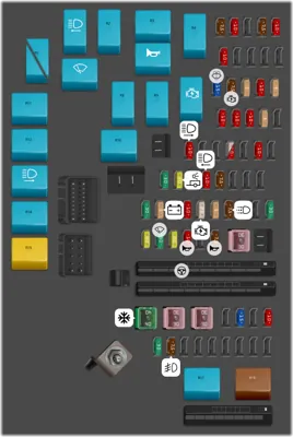
The first diagram applies to the TMC-style fuse box layout. It covers hybrid power control, fuel injection, inverter cooling, ABS, lighting, washers, cooling fans and relays. Some positions have different ratings depending on whether the car has a 1.8 or 2.0 engine.
| Position | Amperage [A] | Protected circuit / function |
|---|---|---|
| 1 | 7.5 | Power Control Unit (PCU) circuit No. 2 |
| 2 | 10 | Power Control Unit (PCU) circuit No. 1 |
| 4 | 7.5 | PM-IGCT hybrid power management circuit |
| 5 | 10 | IGCT circuit No. 2 |
| 6 | 10 | EFI No. 5 – electronic fuel injection |
| 11 | 15 | WASHER – windshield washer system |
| 12 | 7.5 | IGN – ignition circuit |
| 13 | 5 | Engine control power supply ECU-IGP No. 1 |
| 14 | 10 | Engine control power supply ECU-IGP No. 3 |
| 15 | 5 | Engine control power supply ECU-IGP No. 2 |
| 16 | 10 | EFI No. 2 – electronic fuel injection |
| 17 | 10 | EFI No. 3 – electronic fuel injection |
| 18 | 10 | Hybrid traction battery cooling fan circuit |
| 19 | 5 | Inverter coolant pump circuit |
| 21 | 10 | H-LP RH – right headlamp |
| 24 | 25 | EFI-MAIN No. 2 – fuel injection; 25 A applies to the 2.0-litre M20A-FXS engine |
| 24 | 10 | EFI-MAIN No. 2 – fuel injection; 10 A applies to the 1.8-litre 2ZR-FXE engine |
| 26 | 10 | Inverter coolant pump circuit No. 2 |
| 28 | 30 | EFI-MAIN No. 1 – fuel injection control |
| 29 | 20 | TOWING-B – trailer and lighting supply |
| 31 | 10 | H-LP LH – left headlamp |
| 32 | 7.5 | H-LP HI – high-beam headlamps |
| 36 | 30 | EFI-MAIN No. 3 – fuel injection control |
| 37 | 5 | BATT-S – 12 V battery circuit |
| 39 | 10 | Capacitor circuit |
| 40 | 25 | IGP-MAIN – ignition power supply |
| 41 | 5 | EFI No. 1 – fuel injection |
| 42 | 7.5 | DRL – daytime running lamps |
| 45 | 30 | D/C CUT circuit |
| 46 | 20 | Direct injection (D-INJ) circuit |
| 47 | 30 | WIPER – windshield wiper system |
| 48 | 20 | Variable Valve Timing (VVT) circuit |
| 49 | 10 | HORN – horn |
| 51 | 7.5 | S-HORN – security alarm siren |
| 53 | 15 | DEICER – windshield de-icer/defroster |
| 55 | 10 | STRG HTR – heated steering wheel |
| 56 | 30 | TOWING-DC/DC circuit |
| 57 | 7.5 | FOG FR – front fog lamps |
| 67 | 30 | IGCT-MAIN No. 2 circuit |
| 69 | 40 | HTR – heater and air-conditioning system |
| 70 | 30 | FAN No. 1 – engine cooling fan |
| 71 | 30 | FAN No. 2 – engine cooling fan |
| 72 | – | DC/DC – 400 W DC-to-DC converter (rating not specified in source) |
| 73 | – | IGCT-MAIN No. 1 circuit (rating not specified) |
| 74 | – | ABS MTR No. 1 – anti-lock brake pump motor (rating not specified) |
| 75 | – | EPS – electric power steering (rating not specified) |
| 76 | – | INP STD No. 3 circuit (rating not specified) |
| 77 | – | ABS No. 1 – anti-lock braking (rating not specified) |
| 78 | – | ABS No. 2 – anti-lock braking (rating not specified) |
| 79 | – | ABS MAIN – main brake/ABS supply (rating not specified) |
| 80 | – | PTC HTR No. 3 – supplementary electric heater (rating not specified) |
| 81 | – | PTC HTR No. 1 – supplementary electric heater (rating not specified) |
| 82 | – | PTC HTR No. 2 – supplementary electric heater (rating not specified) |
| 87 | – | INP STD No. 1 circuit (rating not specified) |
| 88 | – | INP STD No. 2 circuit (rating not specified) |
| R1 | – | Relay – H-LP LH left headlamp |
| R2 | – | Relay – EFI-MAIN No. 1 fuel injection control |
| R3 | – | Relay – D-INJ direct injection circuit |
| R4 | – | Relay – IGCT-MAIN No. 1 |
| R5 | – | Relay – VVT circuit, M20A-FXS engine |
| R5 | – | Relay – C/OPN circuit, 2ZR-FXE engine |
| R6 | – | Relay – windshield wipers |
| R7 | – | Relay – horn |
| R8 | – | Relay – IGCT-MAIN No. 2 |
| R9 | – | Relay – de-icer/defroster |
| R10 | – | Relay – IGP ignition |
| R11 | – | Relay – EFI-MAIN No. 2 fuel injection control |
| R12 | – | Relay – inverter coolant pump |
| R13 | – | Relay – right headlamp |
| R14 | – | Relay – engine cooling fan No. 3 |
| R15 | – | Relay – EFI-MAIN No. 3 fuel injection control |
| R16 | – | Relay – high-beam headlamps |
| R17 | – | Relay – engine cooling fan No. 1 |
| R18 | – | Relay – engine cooling fan No. 2 |
WASHER at position 11, 15 A protects the washer system. EFI-MAIN NO.2 at position 24 is specified as 25 A for the 2.0 M20A-FXS and 10 A for the 1.8 2ZR-FXE. Position R5 also has a different relay designation by engine: VVT on the M20A-FXS versus C/OPN on the 2ZR-FXE. Do not substitute ratings or relay types between these engines.
Engine compartment: alternative 2ZR-FXE / 2ZR-FXB layout
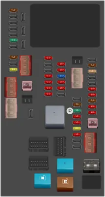
This second configuration is found on selected vehicles built outside the TMC factory arrangement. Its numbered slots do not correspond automatically to the first table. Match the appearance of your under-hood box, the engine identification and the vehicle’s production specifications before using these positions.
| Position | Amperage [A] | Protected circuit / function |
|---|---|---|
| 1 | 7.5 | P/OUTLET No. 2 – 12 V power outlet |
| 6 | 30 | DEF – rear window defogger |
| 8 | 7.5 | FOG FR – front fog lamps |
| 10 | 20 | ENG W/PMP – engine coolant pump |
| 13 | – | PBD – powered tailgate (rating not specified) |
| 14 | – | HTR – heating and air-conditioning (rating not specified) |
| 18 | – | FAN No. 2 – engine cooling fan (rating not specified) |
| 20 | 30 | FAN No. 1 – engine cooling fan |
| 23 | 10 | STRG LOCK-IG2 – steering lock, central locking and starting circuits |
| 26 | 10 | EFI No. 2 – electronic fuel injection |
| 27 | 10 | EFI No. 3 – electronic fuel injection |
| 28 | 10 | INJ – fuel injectors |
| 29 | 10 | ECU-IG2 No. 1 – engine controller, hybrid powertrain and cruise control |
| 30 | 10 | PM-IGCT – hybrid power supply |
| 31 | 10 | IGCT No. 2 – hybrid control circuit |
| 32 | 15 | BATT FAN – hybrid battery cooling fan |
| 33 | 10 | PCU FR – hybrid powertrain and cruise control |
| 34 | 10 | INV W/PMP – inverter coolant pump |
| 37 | – | IGCT-IG – hybrid powertrain and cruise control (rating not specified) |
| 38 | – | ABS MTR No. 3 – anti-lock brake pump motor (rating not specified) |
| 39 | – | ABS MTR No. 1 – anti-lock brake pump motor (rating not specified) |
| 41 | 7.5 | S-HORN – security alarm siren |
| 42 | 30 | WIPER – windshield wipers |
| 43 | 10 | ETCS – electronic throttle control |
| 44 | 10 | HORN – horn |
| 45 | 20 | EFI-MAIN – fuel injection control |
| 46 | 10 | H-LP HI – high-beam headlamps |
| 50 | 7.5 | DRL – daytime running lamps |
| 51 | 5 | BATT-S – battery supply circuit |
| 54 | 10 | ABS No. 3 – anti-lock braking system |
| 55 | 10 | ABS No. 2 – anti-lock braking system |
| 56 | 7.5 | MAYDAY – emergency SOS calling system |
| 57 | 10 | H-LP RH – right headlamp |
| 58 | 10 | H-LP LH – left headlamp |
| 59 | 30 | ABS MTR No. 2 – brake/ABS pump motor |
| 60 | – | ABS-MAIN – main ABS circuit (rating not specified) |
| 62 | – | J/B-B junction block circuit (rating not specified) |
| 63 | 80 | GLOW circuit |
| R1 | – | Relay – IGCT hybrid power control |
| R2 | – | Relay – engine cooling fan No. 3 |
| R3 | – | Relay – engine coolant pump |
| R4 | – | Relay – engine cooling fan No. 2 |
In this configuration, P/OUTLET NO.2 at position 1, 7.5 A can supply an additional 12 V outlet. The windshield wiper circuit is listed as WIPER at position 42, 30 A. These position numbers should not be transferred to the TMC fuse box.
Passenger compartment: 2024 TDB fuse panel
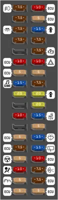
This cabin fuse arrangement is labelled TDB Made in the source documentation. It covers lighting, radio, diagnostics, body/engine control electronics, the rear wiper and washers. Not every fuse position is necessarily populated.
| Position | Amperage [A] | Protected circuit / function |
|---|---|---|
| 1 | 7.5 | FOG RR – rear fog lamps |
| 2 | 7.5 | OBD – on-board diagnostic connector |
| 3 | 7.5 | DOME – interior lighting |
| 4 | 7.5 | DOOR BACK – rear door/tailgate circuit |
| 6 | 10 | ECU-DCC No. 2 – electronic control unit |
| 7 | 5 | ECU-DCC No. 1 – electronic control unit |
| 8 | 15 | RADIO – audio unit |
| 9 | 20 | DOOR R/R – right rear door circuit |
| 11 | 10 | STRG LOCK – steering column lock |
| 13 | 5 | ECU-ACC – electronic control unit accessory feed |
| 14 | 7.5 | ECU-IG1 No. 3 – electronic control unit |
| 15 | 5 | EPS-IG1 – electric power steering |
| 16 | 10 | A/BAG-IG2 – airbag control circuit |
| 17 | 5 | METER-IG2 – instrument cluster |
| 18 | 5 | ECU-IG2 No. 3 – electronic control unit |
| 19 | 10 | ECU-B No. 2 – electronic control unit |
| 20 | 5 | ECU-B No. 1 – electronic control unit |
| 21 | 15 | D/L – central door locking |
| 22 | 7.5 | STOP – brake and stop lamp circuits |
| 23 | 7.5 | AM2 – starter and ignition supply |
| 24 | 10 | HAZ – hazard warning lamps |
| 25 | 5 | PANEL – instrument panel illumination |
| 26 | 7.5 | TAIL – tail and exterior lighting |
| 27 | 20 | DOOR – central door locking |
| 28 | 20 | DOOR R/L – left rear door circuit |
| 29 | 15 | P/OUTLET No. 1 – 12 V power outlet |
| 30 | 5 | SFT LOCK-ACC – automatic transmission shift lock |
| 31 | 15 | WASHER – windshield washer |
| 32 | 15 | WIPER RR – rear window wiper |
| 33 | 10 | ECU-IG1 No. 4 – electronic control unit |
| 34 | 7.5 | BKUP LP – reversing lamps |
| 35 | 7.5 | ECU-IG1 No. 2 – electronic control unit |
| 36 | 5 | ECU-IG1 No. 1 – electronic control unit |
Useful reference points in this cabin panel include RADIO at position 8, 15 A, OBD at position 2, 7.5 A, WASHER at position 31, 15 A and WIPER RR at position 32, 15 A.
Where is the cigarette lighter or 12 V outlet fuse?
For the alternative 2ZR engine compartment layout, P/OUTLET NO.2 at position 1 is 7.5 A. In the TDB passenger compartment table, P/OUTLET NO.1 appears at position 29, 15 A. Confirm which outlets and fuse box variants are fitted to the vehicle; the numbering is not universal.
Common electrical issues
If the radio fails on the TDB configuration, check the 15 A RADIO fuse at position 8. For failed washers, the TMC engine-room WASHER fuse is position 11 at 15 A, whereas the TDB cabin WASHER fuse is position 31 at 15 A. Make sure the named circuit belongs to your actual fuse-box layout before inspecting it.
Do not fit a higher-rated fuse after a failure. If a replacement blows again, inspect the affected wiring and electrical load. For a related Toyota crossover, see the Toyota Yaris Cross XP210 fuse diagrams. The two models use different electrical layouts, so do not transfer fuse positions or ratings between them.
Toyota Corolla Cross fuse box FAQ
Do the 1.8 Hybrid and 2.0 Hybrid use the same fuse ratings?
Not at every position. For example, position 24 (EFI-MAIN NO.2) is 10 A for the 1.8 2ZR-FXE in the TMC layout and 25 A for the 2.0 M20A-FXS. Some relays also differ.
Where is the cabin fuse box?
Below the lower dashboard trim. On left-hand-drive cars, access is generally near the driver’s footwell.
Can these tables be used for a 2022 or 2026 Corolla Cross?
Not without confirming compatibility. The detailed layouts are from selected 2024 European hybrid configurations, and other model years or manufacturing variants may use different assignments.
Fuse information: Toyota Corolla Cross XG10 2024 EU owner documentation for TMC, TDB and 2ZR configurations. Vehicle photograph: Alexander Migl, Wikimedia Commons, CC BY-SA 4.0.