
Toyota MR2 II W20 / SW20 (1989-1999) uses three principal fuse and relay assemblies: inside the passenger compartment, beside the engine at the rear of the car and in the front luggage compartment. Unlike a conventional front-engined Toyota, the MR2 has its engine behind the seats, so starting and injection protections are not necessarily under the front bonnet.
This guide preserves every entry in the three technical tables, including all relays and two separate AM2 fuse positions. The wiring and occupied positions can differ by year, country and engine: naturally aspirated 3S-GE, turbocharged 3S-GTE and North American 5S-FE models are not electrically identical. Match the printed fuse-box cover, engine and build date before replacing any fuse.
Cigarette lighter fuse: in the illustrated passenger compartment arrangement, RAD & CIG (15 A) protects the lighter and radio. Its failure may also affect the clock, power antenna or electric mirrors, depending on equipment.
Toyota MR2 SW20 – locations and access to the three fuse boxes
Passenger compartment, R/B No. 1: find the lower side panel at the driver’s footwell near the sill and left side of the dashboard on a left-hand-drive car. Switch off the ignition, move the seat back and gently remove the lower trim cover to expose the cabin fuse holder. Read the labels before removing a fuse. On right-hand-drive Japanese-market cars the trim and access can be arranged differently.
Rear engine compartment, R/B No. 2: lift the rear engine lid and locate the covered electrical assembly on the left side of the engine bay. Allow hot components and the engine-compartment fan to stop before releasing the plastic cover. The separate EFI, VENT and ECU-IG fuses protect powertrain electronics and rear engine-bay ventilation, not the cooling fans at the front of the car.
Front boot, R/B No. 5: release the front bonnet and locate the fuse and relay housing on the right side of the front luggage compartment. The box contains higher-rated circuits for alternator, ABS, cabin heater, headlights and front cooling fans. Disconnect power according to the workshop procedure before dealing with bolted or high-current links.
Passenger compartment R/B No. 1 – fuse and relay positions
Cabin protection includes radio, cigarette lighter, gauges, wipers, heated rear window, door locks, electric windows and lighting. The 1991 Toyota electrical manual also identifies MIR-HTR (7.5 A) for heated mirrors, which may not be fitted in every year or market. The R1-R3 entries are relays, not additional fuses.
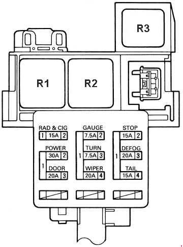
| Position | Amperage [A] | Protected circuit / function | |
|---|---|---|---|
| TAIL | 15 | TAIL – Światła pozycyjne. tylne i obrysowe. oświetlenie tablicy rejestracyjnej oraz podświetlenie zegara. wskaźników. radia i panelu klimatyzacji. Obejmuje też przekaźnik tylnych świateł i sterowanie chowanymi reflektorami. | TAIL: side lamps, tail lamps, number plate lights, clock, instrument, radio and A/C illumination; tail-light relay and retractable headlamp control |
| RAD/CIG | 15 | RAD & CIG – Radio i zapalniczka. zegar. automatyczna antena. lusterka elektryczne. a zależnie od wersji także centralny sterownik SRS. blokada wybieraka automatu. alarm oraz przekaźniki ogrzewania. | RAD & CIG: radio, cigarette lighter, clock, power antenna and mirrors; some versions also supply SRS, automatic shift interlock, alarm and heater relays |
| GAUGE | 7.5 | GAUGE – Zestaw wskaźników i kontrolek. sterowniki ABS. klimatyzacji. SRS. wspomagania. tempomatu i zamków oraz czujniki paliwa. oleju i hamulca postojowego. | GAUGE: instrument cluster and warning lamps, ABS, A/C, SRS, power steering, cruise and door-lock controllers, fuel and oil sensors and parking-brake switch |
| TURN | 7.5 | TURN – Kierunkowskazy i ich kontrolki. przełącznik i przerywacz kierunkowskazów oraz światła awaryjne. | TURN: direction indicators, flasher and hazard warning controls |
| WIPER | 20 | WIPER – Silnik wycieraczek. pompka spryskiwacza i przełącznik zespolony wycieraczek. | WIPER: windscreen wiper motor, washer pump and stalk switch |
| DEFOG | 20 | DEFOG – Ogrzewanie tylnej szyby i jego przekaźnik. | DEFOG: heated rear window and defogger relay |
| STOP | 15 | STOP – Światła hamowania. dodatkowa lampa STOP. wyłącznik przy pedale. sterowniki ABS. tempomatu i silnika oraz blokada wybieraka automatu. | STOP: brake lamps, high-level stop light, brake pedal switch, ABS, cruise and engine control, automatic shift lock |
| DOOR | 20 | DOOR – Centralny zamek. sterownik zamków i siłowniki obu drzwi. | DOOR: door locking ECU and both door lock actuators |
| POWER | 30 | POWER – Elektryczne podnośniki szyb. ich przełączniki. główny przekaźnik zasilania i sterowanie centralnym zamkiem. | POWER: power window regulators, switches, main relay and some central locking control |
| PANEL | 7.5 | PANEL – Podświetlenie przyrządów. popielniczki. zegara. radia i panelu klimatyzacji oraz regulator natężenia oświetlenia. zależnie od rynku i wyposażenia. | PANEL: instrument, ashtray, clock, radio and climate illumination with dimmer, variant-dependent |
| MIR-HTR | 7.5 | MIR-HTR – Podgrzewanie lusterek zewnętrznych. Pozycja z dokumentacji elektrycznej 1991; w innych wersjach jej obsadzenie może się różnić. | MIR-HTR: heated door mirrors; position documented for the 1991 wiring and not populated on every version |
| R1 | – | Ogrzewanie tylnej szyby | Heated rear-window relay |
| R2 | – | Światła pozycyjne i tylne | Side and rear lamps relay |
| R3 | – | Przerywacz kierunkowskazów | Direction indicator flasher relay |
Engine compartment R/B No. 2 – EFI, VENT, ECU-IG and relays
EFI (15 A) supplies injection ECU, fuel pump controls and some engine sensors, including turbo boost control on equipped 3S-GTE cars. VENT (20 A) serves the cooling fan in the rear engine compartment. ECU-IG (7.5 A) powers several controls when ignition is switched on. The four associated relays are retained below.

| Position | Amperage [A] | Protected circuit / function | |
|---|---|---|---|
| EFI | 15 | EFI – Sterownik silnika i układ wtrysku paliwa. złącze diagnostyczne. pompa paliwa i jej przekaźnik. regulator biegu jałowego. sonda lambda. układy EGR oraz T-VIS. a w wersji turbo także elektrozawory doładowania. | EFI: engine ECU, fuel injection, diagnostic connector, fuel pump relay, idle valve, lambda sensor, EGR and T-VIS; turbocharger boost solenoids on 3S-GTE |
| VENT | 20 | VENT – Wentylator chłodzenia komory silnika i jego przekaźnik. | VENT: rear engine compartment cooling fan and relay |
| ECU-IG | 7.5 | ECU-IG – Zasilanie sterownika silnika po włączeniu zapłonu. ABS. alternatora. wentylatora komory silnika. tempomatu. anteny elektrycznej. świateł cofania. czujnika prędkości i automatycznej skrzyni. | ECU-IG: ignition-switched feed for engine ECU, ABS, alternator, rear engine ventilation, cruise, power antenna, reversing lamps, speed sensor and automatic transmission |
| R1 | – | Główny przekaźnik zapłonu | Main ignition relay |
| R2 | – | Główny przekaźnik EFI | EFI engine management relay |
| R3 | – | Przekaźnik otwierający obwód pompy paliwa | Fuel pump circuit-opening relay |
| R4 | – | Przekaźnik wentylatora komory silnika | Rear engine compartment cooling fan relay |
Front luggage compartment R/B No. 5 – all fuses and eight relays
This assembly houses alternator and cabin distribution links, ABS supply, blower, radiator cooling fans, lighting and the electric pop-up headlamp mechanisms. AM2 (40 A) and AM2 (7.5 A) protect different circuits in the same overall area: they are not alternative fuse ratings to swap in a single socket. For pop-up headlights, RTR (30 A) powers the raising/retracting mechanism, while HEAD-L and HEAD-R (15 A each) protect the individual headlight circuits.
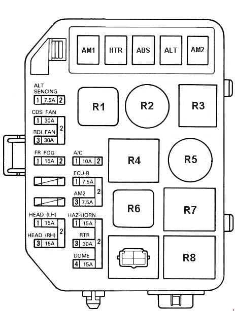
| Position | Amperage [A] | Protected circuit / function | |
|---|---|---|---|
| AM1 | 50 | AM1 – Główne zabezpieczenie obwodów FR FOG. STOP. DEFOG. TAIL. POWER. DOOR i PANEL. a przez stacyjkę również RAD & CIG. GAUGE. TURN i WIPER. | AM1: main power to fog lights, brake lights, defogger, tail lamps, windows, doors and instrument lighting; ignition-switched radio, gauges, indicators and wipers |
| HTR | 40 | HTR – Główne zasilanie ogrzewania i nawiewu oraz przekaźnika nagrzewnicy i części układów klimatyzacji. | HTR: heater blower and main heating/A/C supply |
| ABS | 80 | ABS – Wysokoprądowe zasilanie zespołu hydraulicznego ABS w wyposażonych w niego wersjach. | ABS: high-current ABS hydraulic unit supply, ABS-equipped versions only |
| ALT | 120 | ALT – Główny obwód alternatora. zasilanie reflektorów. ECU-B. AM2. HAZ-HORN. RTR. DOME i przekaźnika zapłonu. | ALT: alternator main power, headlights, ECU-B, AM2, hazard/horn, retractable lamps, interior lighting and ignition relay |
| AM2 | 40 | AM2 – Wysokoprądowy obwód stacyjki oraz zasilanie obwodu ALT SENCING. | AM2: high-current ignition switch supply and alternator sensing |
| ALT-S | 7.5 | ALT SENCING – Pomiar i regulacja napięcia alternatora. | ALT-S: alternator voltage sensing and control |
| CDS FAN | 30 | CDS FAN – Wentylatory chłodnicy oraz skraplacza klimatyzacji. przekaźniki wentylatorów nr 2 i nr 3. | CDS FAN: radiator and A/C condenser cooling fans, fan relays 2 and 3 |
| RDI FAN | 30 | RDI FAN – Wentylator chłodnicy i przekaźnik wentylatora nr 1. | RDI FAN: front radiator cooling fan and fan relay 1 |
| FR FOG | 15 | FR FOG – Przednie światła przeciwmgielne. ich przełącznik i przekaźnik oraz sterowanie mechanizmem chowanych reflektorów. | FR FOG: front fog lamps and relay and associated retractable lamp controls |
| HEAD-L | 15 | HEAD (LH) – Lewy reflektor. przełącznik świateł. kontrolka świateł drogowych oraz sterowanie chowanymi lampami. | HEAD (LH): left headlamp, light switch, main-beam tell-tale and retractable lamp circuitry |
| HEAD-R | 15 | HEAD (RH) – Prawy reflektor. przełącznik świateł. kontrolka świateł drogowych oraz sterowanie chowanymi lampami. | HEAD (RH): right headlamp, light switch, main-beam tell-tale and retractable lamp circuitry |
| A/C | 10 | A/C – Sprzęgło sprężarki klimatyzacji. sterownik. wzmacniacz. czujnik ciśnienia. przekaźnik sprzęgła i regulacja biegu jałowego. | A/C: compressor clutch, control ECU, pressure switch, clutch relay and idle adjustment |
| ECU-B | 7.5 | ECU-B – Zasilanie sterowników ABS. SRS i tempomatu oraz kontrolki poduszek powietrznych. | ECU-B: ABS, SRS and cruise control ECU supply and airbag warning circuit |
| AM2 | 7.5 | AM2 – Sterowanie zapłonem. rozruchem i pracą silnika. kontrolka ładowania. wtryskiwacz rozruchowy. przekaźniki wentylatorów. klimatyzacja i blokada rozruchu zależna od rodzaju skrzyni. | AM2: separate 7.5 A ignition/starting control feed for charging lamp, cold-start injector, fan relays, A/C and starter interlock |
| HAZ | 15 | HAZ-HORN – Klakson i jego przekaźnik. kierunkowskazy. światła awaryjne. przerywacz oraz sygnał alarmu przeciwkradzieżowego. | HAZ-HORN: horn, horn relay, turn indicators, hazard lights, flasher and antitheft alarm |
| RTR | 30 | RTR – Przekaźnik i silniki wysuwania oraz chowania lewego i prawego reflektora. | RTR: motors and relay for raising and retracting both pop-up headlights |
| DOME | 15 | DOME – Oświetlenie wnętrza. drzwi. stacyjki i tylnego bagażnika. zegar. kontrolka otwartych drzwi. antena automatyczna i wybrane elementy audio oraz sygnalizacji pasów. | DOME: cabin, door, ignition-key and rear boot lighting, clock, door warning, power antenna and selected audio/seatbelt circuits |
| R1 | – | Przekaźnik ogrzewania i nawiewu | Heater and cabin blower relay |
| R2 | – | Przekaźnik reflektorów | Headlamp relay |
| R3 | – | Przekaźnik klaksonu | Horn relay |
| R4 | – | Przekaźnik wentylatora nr 2 | Cooling fan relay 2 |
| R5 | – | Przekaźnik wentylatora nr 1 | Cooling fan relay 1 |
| R6 | – | Główny przekaźnik wentylatorów | Main cooling fan relay |
| R7 | – | Przekaźnik wentylatora nr 3 | Cooling fan relay 3 |
| R8 | – | Przekaźnik przednich świateł przeciwmgielnych | Front fog light relay |
Differences by year, country and engine
The SW20 is a second-generation MR2, distinct from the AW11 and W30 models. Toyota’s 1991 wiring documentation identifies the locations R/B No. 1, 2 and 5 and the MIR-HTR circuit. The 5S-FE North American engine, 3S-GE European/Japanese versions and 3S-GTE turbo do not necessarily use the same engine control harness and relays. Cars without ABS or mirror heating can have unoccupied fuse positions.
Equipment revisions during 1989-1999 mean that a schematic verified for 1991 is a technical reference, not a guarantee of identical wiring on every later facelift. Check the fitted module, stamped labels and the correct Toyota wiring diagram for the VIN.
MR2 electrical problems – what to check first?
Pop-up headlights do not rise: inspect front RTR (30 A), its motor relay and the linkage. If the lamps rise normally but do not illuminate, check the left and right HEAD fuses (15 A) and the lamp/ground connections. These are different faults with different circuits.
Starter turns but the engine will not fire: check EFI (15 A) in the rear engine bay and the EFI and fuel pump circuit-opening relays. Inspect ECU fault codes, fuel pump operation and the immobiliser where fitted; do not keep replacing fuses that immediately blow.
Windows or central locking have failed: cabin POWER (30 A) protects the windows, and DOOR (20 A) protects locks. The main front AM1 (50 A) also supplies multiple accessory circuits.
Cooling fans stop operating: distinguish the front RDI FAN (30 A) and CDS FAN (30 A) circuits from rear engine compartment VENT (20 A). The front radiator and A/C condenser fans are physically separate from the rear ventilation fan.
No radio or cigarette lighter: check RAD & CIG (15 A) in the cabin. Remove an aftermarket USB charger and check the lighter’s inner contacts for a short before fitting a replacement.
Related Toyota electrical diagrams
The early Toyota Picnic / Ipsum (1996-2001) uses related Toyota 3S-series powertrain technology on certain engines, but its fuse locations and numbers do not match the MR2. The Toyota Avensis I T22 (1997-2002) provides another example of the wider 3S engine family in a different electrical platform.
Technical reference: Toyota MR2 SW20 factory electrical wiring information, including the 1991 fuse and relay arrangement and 3S-GE/3S-GTE/5S-FE engine variants. Check the manual for the actual year and market.