
The Toyota Yaris Cross XP210 has fuse boxes inside the passenger compartment and under the bonnet. The layout varies with the engine, market and model year. The tables below reproduce the positions documented for the European 2022 Hybrid with the 1.5-litre M15A-FXE engine and, separately, for a 2023 1.5-litre M15A-FKS petrol model sold in selected markets.
Do not substitute the fuse positions of a petrol car for those of a hybrid. Different drivetrain equipment and electrical systems require different schematics. Before replacing a fuse, match the physical layout, label and rating to your particular vehicle.
Where are the Toyota Yaris Cross fuse boxes?
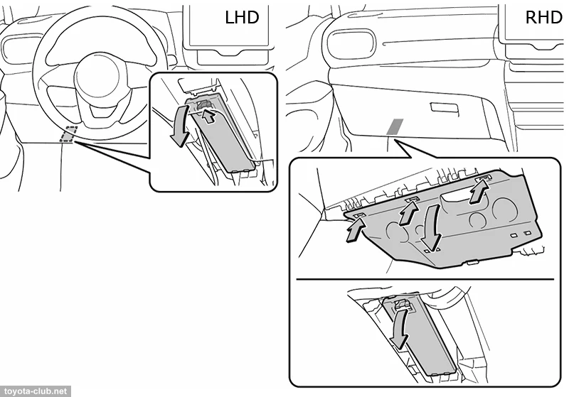
Dashboard: on left-hand-drive vehicles, the interior fuse box is below the dashboard on the driver’s side behind a lower trim cover. With right-hand drive, it can be reached from beneath the dash on the opposite side, possibly requiring removal of an additional trim panel. Switch the ignition off before opening the cover.
Engine bay: the main fuse boxes are in covered housings near the 12 V battery and the side of the engine compartment. Switch the car off and, on hybrid models, confirm the READY indicator is off. Release the lid clips carefully and identify which box and diagram match your car. Never touch orange high-voltage wiring.
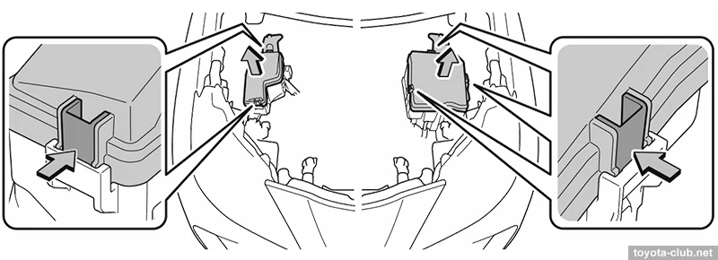
Toyota Yaris Cross Hybrid 2022 – 1.5 M15A-FXE engine compartment
This configuration corresponds to the 2022 European hybrid. Its under-bonnet box includes injection system fuses, the radiator cooling fan, braking systems, electric power steering and ten relays, labelled R1-R10. The table preserves both fuse and relay entries exactly as documented, including unused slots.
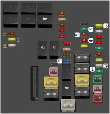
| Position | Amperage [A] | Protected circuit / function |
|---|---|---|
| R1 | – | EFI-MAIN NO.3 – main fuel injection relay |
| R2 | – | A/F HTR – air/fuel-ratio sensor heater relay |
| R3 | – | EFI-MAIN NO.2 – main fuel injection relay |
| R4 | – | FAN NO.1 – cooling fan relay |
| R5 | – | EFI-MAIN NO.1 – main fuel injection relay |
| R6 | – | HORN – horn relay |
| R7 | – | IGP – ignition and starting circuit relay |
| R8 | – | WIPER – windscreen wiper relay |
| R9 | – | VVT – variable valve timing relay |
| R10 | – | S-HORN – security alarm siren relay |
| 1 | 7.5 | INJ – fuel injector control |
| 2 | 5 | EFI NO.5 – electronic fuel injection |
| 3 | 7.5 | EFI NO.2 – electronic fuel injection |
| 4 | 10 | EFI NO.3 – electronic fuel injection |
| 5 | 10 | EFI NO.4 – electronic fuel injection |
| 6 | 10 | ECU-IGP NO.3 – electronic control unit power supply |
| 7 | 5 | ECU-IGP NO.2 – electronic control unit power supply |
| 8 | 7.5 | ECU-IGP NO.1 – electronic control unit power supply |
| 9 | 15 | WASHER – windscreen washers |
| 10 | – | EMPTY – unused position |
| 11 | 30 | WIPER – windscreen wipers |
| 12 | 7.5 | S-HORN – security alarm siren |
| 13 | 10 | HORN – horn |
| 14 | 20 | VVT – variable valve timing system |
| 15 | 20 | TOWING-B NO.1 – trailer lighting supply |
| 16 | 25 | EFI-MAIN NO.2 – main fuel injection supply |
| 17 | 10 | CAPACITOR – capacitor supply |
| 18 | 10 | A/F HTR – air/fuel-ratio sensor heater |
| 19 | 30 | EFI-MAIN NO.3 – main fuel injection supply |
| 20 | 7.5 | EFI NO.1 – electronic fuel injection |
| 21 | 20 | EFI-MAIN NO.1 – main fuel injection supply |
| 22 | 25 | GP-MAIN – main electrical power supply |
| 23 | 30 | J/C – J/C CUT circuit |
| 24 | 7.5 | SPARE1 – spare fuse |
| 25 | 20 | SPARE2 – spare fuse |
| 26 | 25 | SPARE3 – spare fuse |
| 27 | – | EMPTY – unused position |
| 39 | – | INP STD NO.1-2 circuit; source does not provide rating |
| 40 | – | INP STD NO.1-1 circuit; source does not provide rating |
| 41 | – | PTC HTR – supplementary electric heater; source does not provide rating |
| 28 | 30 | FAN NO.1 – engine cooling fan |
| 29 | 40 | ABS-MAIN – main ABS electrical supply |
| 30 | 30 | ABS NO.2 – ABS power supply |
| 31 | 50 | ABS NO.1 – ABS power supply |
| 32 | 60 | FAN – engine cooling fan |
| 33 | 80 | SUB R-B ALT circuit |
| 34 | 120 | DC/DC – 400 W DC/DC converter circuit |
| 35 | 80 | INP STD NO.1-3 circuit |
| 36 | 80 | EPS – electric power steering |
| 37 | 60 | STD P/I NO.1 circuit |
| 38 | 80 | SUB R/B BATT circuit |
Common circuits: WASHER at position 9 is 15 A, WIPER at position 11 is 30 A, HORN at position 13 is 10 A and EPS at position 36 is 80 A. High-current fuse work should be performed by someone qualified to service the 12 V electrical system.
Toyota Yaris Cross Hybrid 2022 – passenger compartment
This separate cabin fuse panel contains 41 documented entries, including the audio system, 12 V socket, USB power, central locking, electric windows, instruments, diagnostic port and airbag controls.
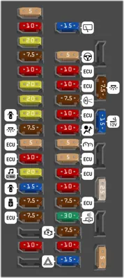
| Position | Amperage [A] | Protected circuit / function |
|---|---|---|
| 1 | 5 | IDLE UP circuit |
| 2 | 10 | MIR HTR – heated door mirrors |
| 3 | 20 | DOOR R/R – right rear power window |
| 4 | 7.5 | OBD – diagnostic connector |
| 5 | 10 | ECU-B – ECU power supply |
| 6 | 20 | DOOR F/R – front right power window |
| 7 | 20 | DOOR R/L – rear left power window |
| 8 | 20 | DOOR F/L – front left power window |
| 9 | 7.5 | DOME CUT – interior lighting |
| 10 | 5 | ECU-DCC NO.1 – body ECU supply |
| 11 | 10 | ECU-DCC NO.2 – body ECU supply |
| 12 | 20 | RADIO – radio and audio system |
| 13 | 15 | D/L – central door locking |
| 14 | 7.5 | USB NO.1 – USB power socket |
| 15 | 7.5 | ECU-ACC – accessory ECU power supply |
| 16 | – | EMPTY – unused position |
| 17 | 10 | DOOR BACK circuit |
| 18 | – | EMPTY – unused position |
| 19 | 15 | WIPER RR – rear window wiper |
| 20 | 5 | EPS-IGR – electric power steering |
| 21 | 10 | ECU-IGR NO.1 – ECU power supply |
| 22 | 10 | ECU-IGR NO.4 – ECU power supply |
| 23 | 7.5 | BKUP LP – reversing lights |
| 24 | 10 | ECU-IGR NO.2 – ECU power supply |
| 25 | 10 | A/BAG-IGR – airbag SRS control circuit |
| 26 | 5 | METER-IGR – instrument cluster |
| 27 | 5 | ECU-IGR NO.3 – ECU power supply |
| 28 | 10 | ECU-B NO.2 – ECU power supply |
| 29 | 10 | STOP – brake lights |
| 30 | 7.5 | ECU-B NO.1 – ECU power supply |
| 31 | 30 | TOWING – vehicle and trailer lighting supply |
| 32 | 7.5 | AM2 – starter circuit |
| 33 | 10 | STRG LOCK – steering column lock |
| 34 | 15 | HAZ – turn signals and hazard lights |
| 35 | – | EMPTY – unused position |
| 36 | 7.5 | DOME – interior lighting |
| 37 | 15 | P/OUTLET MO.1 – 12 V accessory socket (label as shown in source table) |
| 38 | – | EMPTY – unused position |
| 39 | 25 | DOOR DBL/L – door double locking |
| 40 | – | EMPTY – unused position |
| 41 | 5 | DCM – telematics/data communications module |
12 V outlet: position 37, 15 A, labelled P/OUTLET MO.1 in the source table. Radio: position 12, RADIO, 20 A. USB charging: position 14, USB NO.1, 7.5 A. OBD diagnostic connector: position 4, OBD, 7.5 A. Check the actual cover label if your model uses a different spelling or fuse box arrangement.
Toyota Yaris Cross petrol 2023 – 1.5 M15A-FKS main engine fuse box
Selected-market petrol versions use different under-hood fuse and relay arrangements from the European Hybrid. This table covers the 2023 M15A-FKS configuration, including the injection, ignition, starter, stop-start, cooling fan and wiper systems. A dash in the rating column means the original table did not provide a fuse amperage, not that any fuse rating is acceptable.
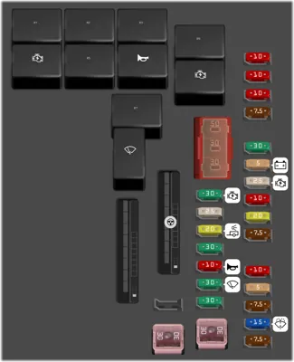
| Position | Amperage [A] | Protected circuit / function |
|---|---|---|
| 2 | 30 | ST NO.1 – starter motor |
| 3 | 25 | EFI-MAIN NO.2 – main fuel injection supply |
| 4 | 20 | TOWING-B – trailer lighting supply |
| 5 | 30 | EFI-MAIN NO.1 – main fuel injection supply |
| 6 | 10 | HORN – horn |
| 7 | 30 | WIPER – windscreen wipers |
| 8 | 30 | D/C CUT circuit |
| 9 | 10 | EFI NO.3 – electronic fuel injection |
| 10 | 10 | EFI NO.5 – electronic fuel injection |
| 11 | 10 | ECU-IGP NO.3 – ECU power supply |
| 12 | 7.5 | ECU-IGP NO.1 – ECU power supply |
| 13 | 30 | EFI-MAIN NO.3 – main fuel injection supply |
| 14 | 5 | BATT-S NO.1 – battery charging supply |
| 15 | 25 | IGP-MAIN – ignition and starting supply |
| 16 | 10 | A/F HTR – air/fuel-ratio sensor heater |
| 17 | 20 | D-INJ circuit |
| 18 | 7.5 | EFI NO.1 – electronic fuel injection |
| 19 | 10 | EFI NO.4 – electronic fuel injection |
| 20 | 5 | ECU-IGP NO.2 – ECU power supply |
| 21 | 7.5 | INJ – fuel injector control |
| 22 | 15 | WASHER – windscreen washers |
| 23 | 7.5 | EFI NO.2 – electronic fuel injection |
| 24 | – | PTC HTR – supplementary electric heater; rating not specified |
| 25 | – | SUB R/B ALT circuit; rating not specified |
| 26 | – | INP STD NO.1-1 circuit; rating not specified |
| 27 | – | STD P/1 NO.1 circuit; rating not specified |
| 28 | – | EPS – electric power steering; rating not specified |
| 29 | – | SUB R/B BATT circuit; rating not specified |
| 30 | 30 | FAN NO.1 – engine cooling fan |
| 31 | – | ABS NO.1 – anti-lock brake system; rating not specified |
| 32 | – | BBC NO.1 – stop-start system; rating not specified |
| 33 | – | ABS NO.2 – ABS power supply; rating not specified |
| 34 | 30 | BBC NO.2 – stop-start system |
| R1 | – | D-INJ circuit relay |
| R2 | – | A/F HTR – air/fuel-ratio sensor heater relay |
| R3 | – | EFI-MAIN NO.1 – main fuel injection relay |
| R9 | – | EFI-MAIN NO.3 – main fuel injection relay |
| R4 | – | IGP – ignition and starting relay |
| R5 | – | EFI-MAIN NO.2 – main fuel injection relay |
| R6 | – | HORN – horn relay |
| R10 | – | ST NO.1 – starter relay |
| R7 | – | FAN NO.1 – cooling fan relay |
| R8 | – | WIPER – windscreen wiper relay |
| 1 | – | EMPTY – unused position |
2023 petrol – additional engine compartment fuse box
The supplementary fuse and relay panel protects circuits such as the power tailgate, stop-start system, heated steering wheel, parking assistance and audio amplifier, depending on equipment. Use these positions only if your car has the matching additional box.
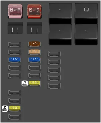
| Position | Amperage [A] | Protected circuit / function |
|---|---|---|
| 1 | 30 | PBD – powered tailgate |
| 2 | 50 | BBC NO.3 – stop-start system power supply |
| 7 | 15 | DEICER – heated windscreen wiper resting area |
| 10 | 7.5 | S-HORN – alarm siren |
| 11 | 5 | IR – parking sensors and park assist |
| 12 | 15 | STRG-HTR – heated steering wheel |
| 15 | 20 | AMP NO.1 – audio amplifier |
| 23 | 20 | AMP NO.2 – audio amplifier |
| R1 | – | IR – parking assistance relay |
| R2 | – | DEICER – windscreen de-icer relay |
| R3 | – | STRG-HTR – heated steering wheel relay |
| R4 | – | S-HORN – security alarm siren relay |
Where are the power outlet, radio and washer fuses?
On the 2022 Hybrid, first inspect the cabin position 37 for the 12 V socket (15 A). Disconnect the accessory before testing. If a new fuse blows again, inspect the socket and attached device rather than fitting a larger fuse.
On the same 2022 Hybrid, the radio is protected by RADIO at cabin position 12 (20 A), while the washer system uses WASHER at engine position 9 (15 A) and the windshield wipers use WIPER at engine position 11 (30 A). Always confirm that the labelled box corresponds to the hybrid, not the 2023 petrol variant.
For another Toyota crossover using a different electrical layout, see the Toyota Corolla Cross XG10 Hybrid fuse diagrams. Do not carry fuse slot numbers between the two models.
Toyota Yaris Cross XP210 fuse box FAQ
Which fuse supplies the cigarette lighter or 12 V outlet?
For the documented 2022 European Hybrid, position 37 in the cabin is 15 A. Its source-table label is P/OUTLET MO.1. Check the actual fuse box lid for the corresponding outlet designation.
Are hybrid and petrol models fitted with the same engine-bay fuse boxes?
No. This guide provides separate listings for the 2022 M15A-FXE Hybrid and 2023 M15A-FKS petrol versions. The layouts cannot safely be treated as interchangeable.
Where is the passenger compartment fuse box?
Behind the lower dashboard cover on the driver’s side on left-hand-drive vehicles. Access can differ on right-hand-drive cars.
Fuse information: Toyota Yaris Cross XP210 2021-2023 documentation, 2022 European Hybrid M15A-FXE and selected-market 2023 petrol M15A-FKS diagrams. Vehicle photograph: Jakub CA, Wikimedia Commons, CC BY-SA 4.0.