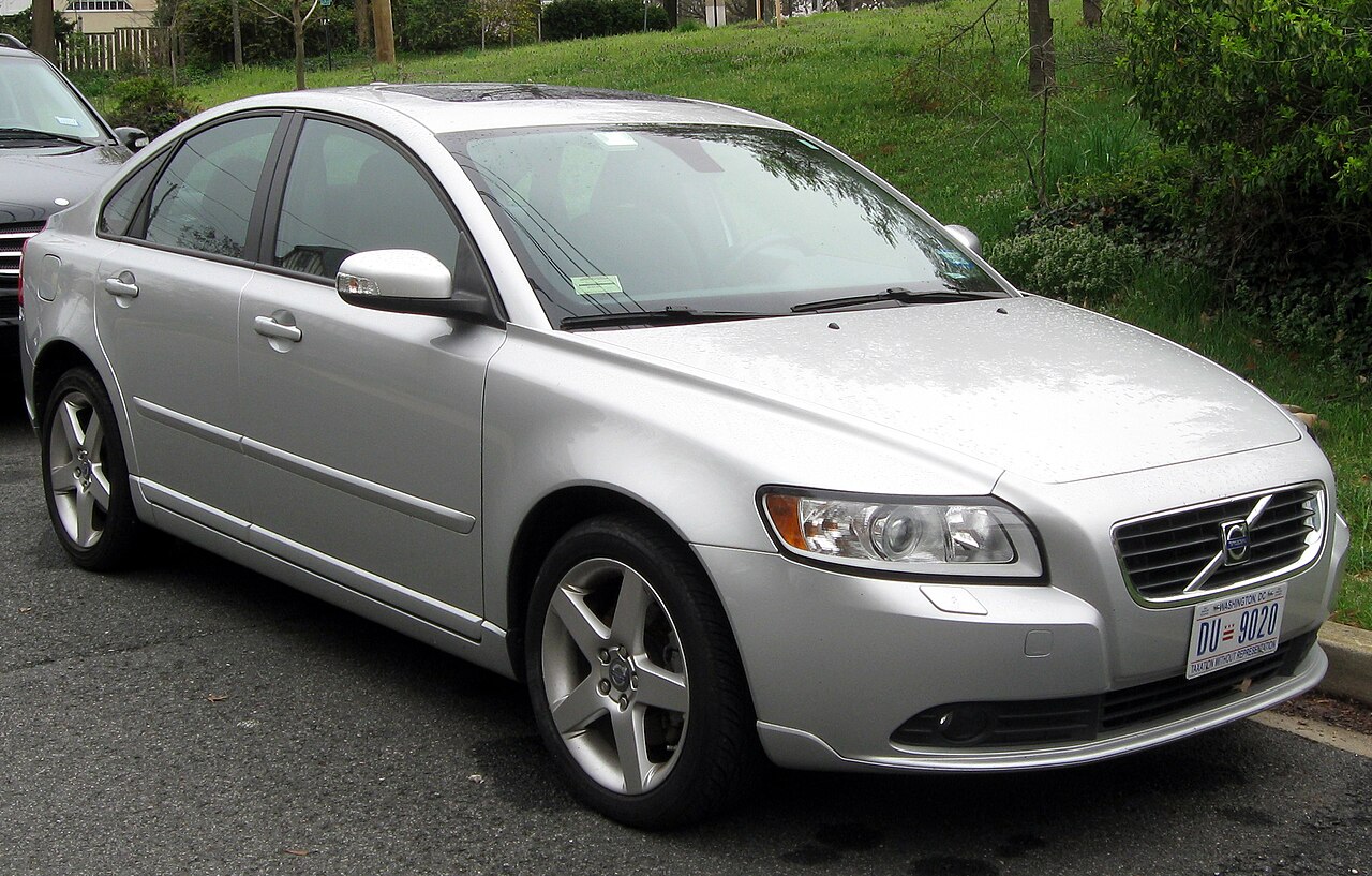
The second-generation Volvo S40 II (2012) is a compact European sedan from Volvo’s P1 family. It has one 36-position engine-bay fuse box beside the 12 V battery and a separate 50-position passenger compartment holder beneath the front passenger glovebox. Certain European DRIVe diesel models with automatic Start/Stop add three supplementary battery and distribution fuses with separate manufacturer identifiers.
This year-specific guide preserves every documented entry, including unused locations, the auxiliary DRIVe positions, both main schematic drawings and the original featured photo. Volvo S40 models have different fuse populations depending on petrol or diesel engine, USA versus European market, AWD and optional equipment. Never fit a fuse of another rating solely because its position number matches a different model year.
Where are the Volvo S40 2012 fuse boxes?
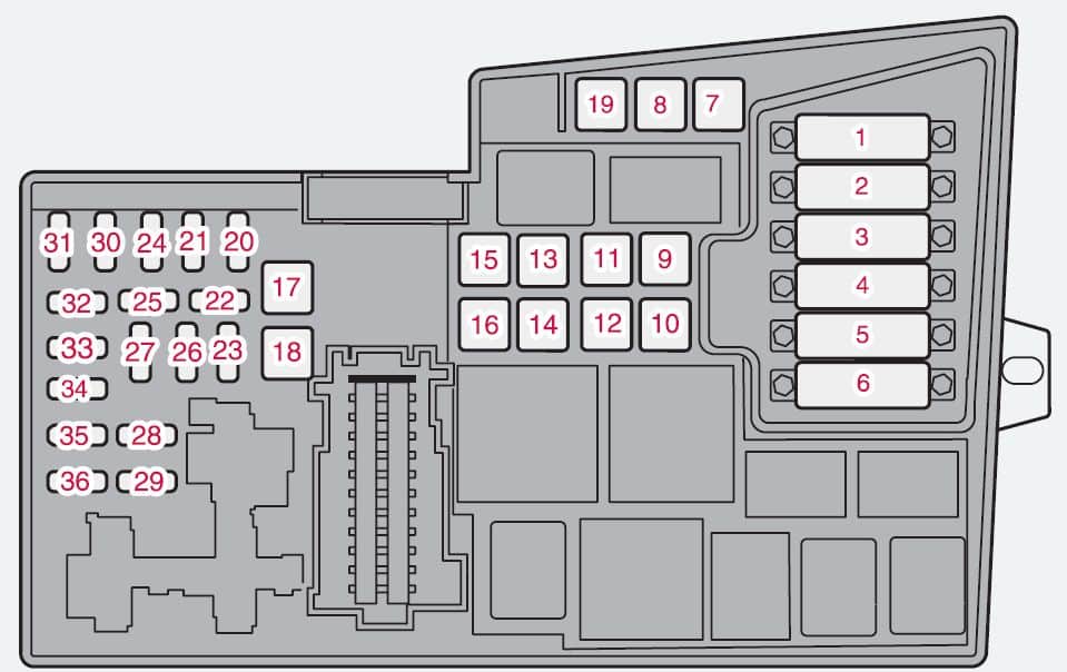
Under the bonnet: the covered unit sits near the vehicle battery and contains high-current protection for the radiator fan, steering, ABS, starter, climate-control blower and engine. Volvo generally recommends trained servicing for the main fuses 1-18; ordinary smaller protection is in slots 19-36.
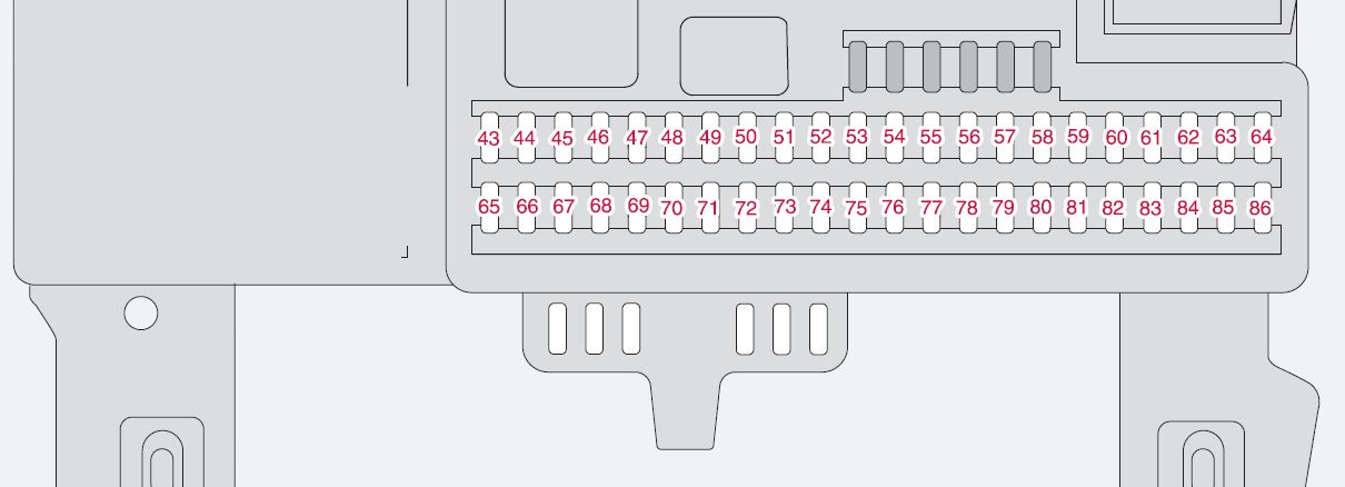
Passenger side: another fuse panel is secured beneath the glovebox. Release the lower trim retaining clips and the two panel locks, lower the panel toward the passenger seat, then refit it securely after checking. These positions are numbered 37-86; do not mistake this holder for the driver’s dashboard end fuse panel found on other Volvo generations.
Volvo S40 2012 under-bonnet fuses 1-36
These 36 fuse entries retain their original ratings and year-dependent alternatives. Front windscreen wipers: engine fuse 17 (30 A); blower motor: fuse 10 (40 A); horn: fuse 20 (15 A); engine controls: ECM/TCM at position 23 as applicable. The ABS hydraulic pump at position 7 requires special attention to region and model year.
| Position | Rating [A] | Protected circuit / function |
|---|---|---|
| 1 | 50 | Radiator cooling fan |
| 2 | 80 | Electric power steering |
| 3 | 60 | First main feed to cabin fuse box |
| 4 | 60 | Second main feed to cabin fuse box |
| 5 | 80 | Optional PTC auxiliary heater |
| 6 | 60 / 70 / – | Diesel glow plug power; 60 A DRIVe or 70 A five-cylinder diesel in specified variants; empty on petrol versions |
| 7 | 40 | ABS hydraulic pump, rated 40 A in the 2012 European reference |
| 8 | 20 | ABS hydraulic valves |
| 9 | 30 | Main engine-management power supply |
| 10 | 40 | Air-conditioning and heating blower motor |
| 11 | 20 | Headlamp washers if fitted |
| 12 | 30 | Heated rear windscreen |
| 13 | 30 | Starter relay feed |
| 14 | 40 | Factory trailer electric supply if fitted |
| 15 | – | Unused in the basic layout |
| 16 | 30 | Main original audio and multimedia power |
| 17 | 30 | Front windscreen wiper motor |
| 18 | 40 | Additional main feed to passenger cabin panel |
| 19 | – | Unused position |
| 20 | 15 | Horn |
| 21 | 20 | Additional fuel-fired cabin heater on selected European cars; otherwise unused |
| 22 | – | Unused position |
| 23 | 10 / 15 | Engine ECM and transmission TCM, model-dependent 10 or 15 A |
| 24 | 20 | Diesel fuel filter heater or crankcase breather PTC, depending on engine |
| 25 | – | CEM function on DRIVe Start/Stop vehicles; unused in the basic general panel for other engines |
| 26 | 15 | Ignition switch |
| 27 | 10 | Air-conditioning compressor clutch control |
| 28 | – | Unused position |
| 29 | 15 | Front fog lamps and/or DRL, where equipped |
| 30 | 10 | Coolant pump associated with Start/Stop, if fitted |
| 31 | 10 | Alternator voltage regulator in selected four-cylinder petrol engines |
| 32 | 10 | Petrol fuel injectors or diesel turbo, airflow and fuel-management controls depending on engine |
| 33 | 20 | Petrol vacuum pump or diesel ECM and fuel-heater controls |
| 34 | 10 | Petrol ignition coils or diesel EGR/glow-plug controls |
| 35 | 15 | A/C relay, engine sensors and solenoids, EVAP, MAF and turbo/VVT hardware depending on engine |
| 36 | 10 | Engine ECM, accelerator-pedal sensors and emissions electronics |
Volvo S40 2012 DRIVe Start/Stop additional fuses
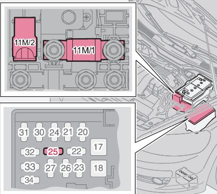
Selected European diesel cars with Start/Stop have supplementary battery distribution positions 11M/1 (125 A) and 11M/2 (15 A), plus 25 (Start/Stop) (10 A) associated with the CEM and auxiliary battery reference supply. They are not the same numbering system as ordinary engine fuse 25. These high-current and battery sensing circuits require vehicle-specific checks.
| Position | Rating [A] | Protected circuit / function |
|---|---|---|
| 11M/1 | 125 | Main 125 A electrical distribution protection for DRIVe Start/Stop, near the battery |
| 11M/2 | 15 | Battery condition and charge-state monitor circuit |
| 25 | 10 | CEM voltage reference for the auxiliary battery on DRIVe diesel Start/Stop variants |
Volvo S40 2012 interior fuses 37-86
The cabin panel covers lighting, comfort electronics, audio, central locking and the power windows. Fuse 45 (15 A) supplies an interior 12 V socket, fuse 57 (15 A) the OBD II diagnostic connector and brake light switch, and fuse 74 (15 A) the fuel pump relay. The front and rear door window circuits have separate protection.
| Position | Rating [A] | Protected circuit / function |
|---|---|---|
| 37 | – | Unused position |
| 38 | – | Unused position |
| 39 | – | Unused position |
| 40 | – | Unused position |
| 41 | – | Unused position |
| 42 | – | Unused position |
| 43 | 15 | Factory radio, Bluetooth and Volvo RTI navigation where fitted |
| 44 | 10 | Airbag and seat-belt pretensioner SRS control and ECM-related circuits |
| 45 | 15 | Cabin 12 V accessory socket including rear-passenger area |
| 46 | 5 | Glovebox, dashboard and footwell lamps |
| 47 | 5 | Interior lighting and optional garage-door transmitter |
| 48 | 15 | Front washer pump |
| 49 | 10 | SRS airbag controller and front passenger occupant sensor |
| 50 | – | Unused position |
| 51 | 10 | Optional PTC heater and diesel fuel-filter heater relay, depending on engine |
| 52 | 5 | Automatic transmission controller TCM and ABS electronics |
| 53 | 10 | Electric steering control feed |
| 54 | 10 | Parking assistance and optional Xenon / active-bending headlamps |
| 55 | 20 | Optional Keyless access module |
| 56 | 10 | Navigation receiver, remote key and alarm siren |
| 57 | 15 | OBD II diagnostic connector and brake pedal/brake light switch |
| 58 | 7.5 | Right high-beam headlamp and auxiliary lamp relay |
| 59 | 7.5 | Left high-beam headlamp |
| 60 | 15 | Driver heated seat if fitted |
| 61 | 15 | Passenger heated seat if fitted |
| 62 | 20 / – | Optional electric sunroof or unused depending on version |
| 63 | 20 | Right rear door electronics, electric window and central lock |
| 64 | 5 | Unused in the basic reference |
| 65 | 5 | Factory audio electronics |
| 66 | 10 | Infotainment control module ICM and climate control |
| 67 | – | Unused position |
| 68 | 5 | Cruise control |
| 69 | 5 | Climate control, rain sensor and optional BLIS/parking functions |
| 70 | – | Unused position |
| 71 | – | Unused position |
| 72 | – | Unused position |
| 73 | 5 | Sunroof controls, overhead console, seatbelt alerts and optional electrochromic mirror |
| 74 | 15 | Fuel pump relay supply |
| 75 | – | Unused position |
| 76 | – | Unused position |
| 77 | 15 | Luggage compartment 12 V socket and Accessory Electronic Module (AEM) |
| 78 | – | Unused position |
| 79 | 5 | Reversing lamp and optional mirror dimming control |
| 80 | – | Unused position |
| 81 | 20 | Left rear door electronics, electric window and lock |
| 82 | 25 | Front passenger door electric window and control |
| 83 | 25 | Driver door electric window and lock |
| 84 | 25 | Electric front passenger seat |
| 85 | 25 | Electric driver seat |
| 86 | 5 | Interior lamp relay, luggage-area lamp and power-seat controls |
S40 12 V outlets, windscreen wipers, horn and OBD II
Interior 12 V outlet: glovebox-area fuse 45 (15 A). Rear luggage area outlet: fuse 77 (15 A) on suitably equipped variants, sometimes shared with the Accessory Electronic Module AEM. If only one outlet fails, inspect its own circuit and socket contacts.
Front wipers: engine fuse 17 (30 A); front washer pump: cabin fuse 48 (15 A). Horn: engine fuse 20 (15 A). OBD II diagnostics: cabin fuse 57 (15 A), which also serves the brake switch. Right and left high beams: cabin 58 and 59 (7.5 A each).
Air-conditioning blower: main engine fuse 10 (40 A). Fuel pump relay: cabin fuse 74 (15 A). Electric windows use cabin fuse 63 (right rear), 81 (left rear), 82 (front right) and 83 (front left). A recurring blown fuse requires diagnosis of motor load and wiring.
Volvo S40 2012 model-year and regional differences
For the 2012 European reference, ABS pump fuse 7 is 40 A and diesel glow plug protection at fuse 6 may be 60 A (DRIVe) or 70 A (five-cylinder diesel). Engine position 23 can be 10 or 15 A depending on ECM/TCM installation. Optional Keyless equipment can use cabin position 55. Optional equipment including heated seats, sunroof, alarm, Xenon headlights, parking assistance and navigation affects which positions are populated.
Compare Volvo S40 2010 and Volvo S40 2011 for adjacent years, or the Volvo C70 II 2010-2013, which shares related components but has different folding-hardtop protection. For the related hatchback, check the Volvo C30 (2010-2013) fuse diagrams, particularly the rear tailgate wiper and DRIVe Start/Stop circuit differences. Do not transfer fuse functions from another model just because the numbering looks similar.
Volvo S40 2012 fuse box FAQ
Where is the cabin fuse box?
Under the front passenger glovebox, behind the removable lower trim.
Which fuse protects the cabin 12 V socket?
Cabin fuse 45 (15 A).
Which fuse supplies the OBD II port?
Cabin fuse 57 (15 A), also associated with the brake-light switch.
Where is the front wiper fuse?
Under-bonnet fuse 17 (30 A); the washer pump uses cabin fuse 48 (15 A).
Why do some S40 fuse positions have multiple ampere values?
The correct value depends on model year, market, engine or equipment. Check the original vehicle label and handbook rather than increasing an installed rating.
Fuse data follows the Volvo S40 2012 owner reference and corresponding European DRIVe variants; original schematic images and featured photograph retained from the Polish article.