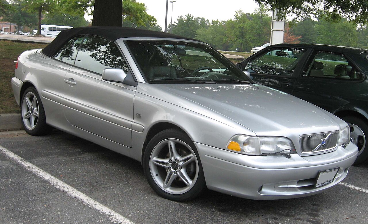
The first-generation Volvo C70 (1999-2000) was sold as a two-door Coupe and a soft-top Convertible. Its original fuse layout has two engine-compartment fuse holders: a main block with 14 high-current fuse positions and four relays, and a supplementary panel with up to 42 numbered positions. The last two supplementary positions are associated with the Convertible folding roof, not the Coupe.
Important: the Coupe and Convertible have different fuse ratings and circuit-breaker arrangements. In particular, main position 9 is unused on the standard Coupe but has a 60 A electric-window fuse on 1999-2000 Convertibles. Main position 7 and supplementary positions 2, 3 and 14 also vary. Match the exact body style, model year and fuse-cover label before changing any protection.
Where are the Volvo C70 1999-2000 fuse boxes?
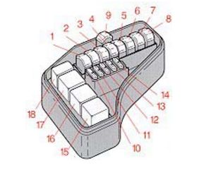
Main fuse and relay box: under the bonnet beneath a clipped plastic cover. It includes high-current supplies for engine cooling, starter, ABS/STC, headlamps and engine controls. Due to the high current involved, repairs to these main circuits should follow Volvo’s service procedures.
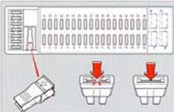
Supplementary fuse holder: also in the engine compartment, under its own cover with a position legend, spare fuses and a puller on some cars. It contains lighting, audio, wipers, 12 V sockets, heating, central locking and electrical accessories. The passenger glovebox-area location used on later C70 II models should not be confused with this generation.
Volvo C70 main high-current fuses 1-14
This table retains both body-style ratings rather than forcing a single number where Volvo documents a variation. Fuse 4 (50 A) supplies ABS/STC and fuse 12 (15 A) protects the fuel pump and injection electronics. Main position 7 is 50 A in a basic Coupe list and 60 A in the 2000 Convertible handbook. Main position 9 is not assigned on Coupe but is 60 A for the Convertible electric windows.
| Position | Rating [A] / type | Protected circuit / function |
|---|---|---|
| 1 | 60 | Engine radiator cooling fan |
| 2 | 50 | First supply feed for the supplementary fuse box |
| 3 | 50 | Main starter supply |
| 4 | 50 | Anti-lock Braking System (ABS) and Stability and Traction Control (STC), if fitted |
| 5 | 50 | Main headlamp feed |
| 6 | 60 | Second supply feed for supplementary fuse box |
| 7 | 50 (Coupe) / 60 (Convertible) | Third supply feed for supplementary box. The 2000 Convertible manual specifies 60 A; standard Coupe reference specifies 50 A |
| 8 | 60 | Engine controller and automatic transmission modules |
| 9 | – (Coupe) / 60 (Convertible) | Unused in the standard Coupe list. In 1999-2000 Convertible, a 60 A fuse supplies the electric windows |
| 10 | 10 | Ignition switch and engine/transmission controller electronics |
| 11 | 15 | Injectors, engine/transmission controls, air conditioning or fuel system |
| 12 | 15 | Fuel pump, injectors and Engine Control Module (ECM) |
| 13 | 15 | Ignition and petrol fuel circuits |
| 14 | 20 | Emission control system |
Volvo C70 relays 15-18
These are four relay positions, not ordinary blade fuses. Relay 15 is the system relay, 17 controls the starter and 18 the air-conditioning system. Position 16 is unused in the documented factory chart.
| Position | Rating [A] / type | Protected circuit / function |
|---|---|---|
| 15 | Relay | System relay (Volvo’s 1999-2000 factory description) |
| 16 | Relay | Unused relay position |
| 17 | Relay | Starter motor relay |
| 18 | Relay | Air-conditioning relay |
Volvo C70 supplementary fuses and breakers 1-42
The panel covers the 12 V cigarette lighter at position 30 (15 A), OBD II electronics at position 5 (15 A), brake lights at 11 (10 A) and front wiper/washer circuits at 34 (25 A). The roof-control positions 41-42 belong to the Convertible and are not standard Coupe equipment.
| Position | Rating [A] / type | Protected circuit / function |
|---|---|---|
| 1 | 10 | Electric boot release |
| 2 | 10 (Coupe) / 15 (Convertible) | Rear fog lamp and warning indicator; 15 A for 1999-2000 Convertible versus 10 A in basic Coupe list |
| 3 | 10 (Coupe) / 15 (Convertible) | Central locking; 15 A for 1999-2000 Convertible versus 10 A in basic Coupe list |
| 4 | 10 | Immobiliser, ABS and automatic gearbox shiftlock |
| 5 | 15 | Air-conditioning control and OBD II diagnostic system |
| 6 | 20 | Additional central locking circuit |
| 7 | 15 | Audio system |
| 8 | 15 | Immobiliser, trip computer and headlamp switch |
| 9 | 30 | Factory audio amplifier |
| 10 | 10 | Remote control for central locking |
| 11 | 10 | Brake lights |
| 12 | 30 | Additional amplifier power circuit |
| 13 | 15 | Hazard flashers, headlamp flash and central locking |
| 14 | 40 (1999 Convertible) / 30 (2000 Convertible) | Heated rear window and exterior mirrors; 40 A for 1999 Convertible or 30 A for 2000 Convertible |
| 15 | 10 | Cabin, door, boot and glovebox lighting, seatbelts and window circuits |
| 16 | 30 | Electric aerial, trailer wiring and optional CD changer |
| 17 | 20 | Front fog lamps, if fitted |
| 18 | 10 | Key-in-ignition reminder and headlamp relay |
| 19 | 15 | Left high-beam headlamp and optional equipment |
| 20 | 15 | Right high-beam headlamp and high-beam indicator |
| 21 | 15 | Left dipped-beam headlamp |
| 22 | 15 | Right dipped-beam headlamp |
| 23 | 10 | Left position/tail lights and number plate illumination |
| 24 | 10 | Right position/tail lights and trailer connections |
| 25 | – | Unused position |
| 26 | 15 | Headlamp switch |
| 27 | 15 | Reversing lamps and turn signals |
| 28 | 25 | Heated front seats, if equipped |
| 29 | 10 | Window and mirror heating, shiftlock, seatbelts, cruise control and convertible roof controls |
| 30 | 15 | Front 12 V accessory outlet and cigarette lighter |
| 31 | 25 | Cabin blower and air-conditioning |
| 32 | 10 | Audio, illumination, climate control; on Convertible, folding roof and boot lock control |
| 33 | – | Unused position |
| 34 | 25 | Front windscreen wipers, washer pump and horn |
| 35 | 10 | Accessories and lighting; on Convertible, window and roof-warning circuits |
| 36 | 15 | Electric seats and seatbelt interlock, depending on equipment |
| 37 | AUT/CB | Automatic circuit breaker: right-side power windows on Convertible; shared windows and sunroof circuit on Coupe |
| 38 | – (Coupe) / AUT/CB (Convertible) | Unused on Coupe; automatic breaker for left-side power window on Convertible |
| 39 | AUT/CB | Automatic circuit breaker for driver power seat |
| 40 | AUT/CB | Automatic circuit breaker for passenger power seat |
| 41 | AUT/CB – Convertible only | First automatic circuit breaker for Convertible folding soft top; not used on Coupe |
| 42 | AUT/CB – Convertible only | Second automatic circuit breaker for Convertible folding roof; not used on Coupe |
Positions 37, 39 and 40 are labelled AUT/CB – automatic circuit breakers, not replaceable blade fuses. Position 38 is also an automatic circuit breaker for the left window in Convertible models, but remains unused in the basic Coupe list.
Differences between Coupe, Convertible, 1999 and 2000
Coupe: fixed metal roof with an optional electric sunroof. Supplementary positions 41-42 are not part of its regular layout; main fuse 9 may be empty. The windows and optional roof can share supplementary breaker 37.
Convertible: power-operated fabric roof and separate protection for the electric windows. The manufacturer’s 1999-2000 guides specify 60 A at main position 9, with supplementary breaker 37 for right-side windows and 38 for left-side windows. Roof breakers 41 and 42, plus control circuits at positions 29, 32 and 35, relate to its soft top.
Year-specific differences: the 1999 Convertible reference lists supplementary 14 at 40 A for rear-window and mirror heating, whereas the 2000 Convertible handbook lists 30 A. The factory Convertible lists also give 15 A for positions 2 and 3, while the Coupe reference has 10 A. Do not use a higher-rating fuse based on another C70 version.
Which fuse should I check for common C70 faults?
Cigarette lighter or 12 V outlet: supplementary 30 (15 A). OBD II diagnostic supply: supplementary 5 (15 A). Brake lamps: supplementary 11 (10 A). Radio and audio amplifier: supplementary 7 (15 A), 9 (30 A) and 12 (30 A). Note that supplementary position 9 is entirely different from main position 9.
Front wipers and washer: supplementary 34 (25 A), also associated with horn functions. Left and right dipped beams: supplementary 21 and 22 (15 A each); high beams 19 and 20 (15 A each).
Convertible power windows: main fuse 9 (60 A), plus breakers 37 and 38. Convertible folding roof: supplementary fuses 29, 32 and 35 (10 A each), plus automatic breakers 41-42. Check battery voltage and mechanical resistance before operating a malfunctioning soft top. Do not bypass its safety interlocks.
Power seats: automatic breakers 39 and 40. A motor jam or overloaded seat mechanism can trip the breaker; do not replace the breaker with a plain fuse or metal bridge.
Volvo C70 I 1999-2000 fuse box FAQ
Which fuse protects the cigarette lighter?
Supplementary fuse 30, rated 15 A.
Is main fuse 9 always empty?
No. The Coupe reference lists it as unused, but the 1999-2000 Convertible uses a 60 A electric-window fuse at this position.
Which positions protect the Convertible roof?
Supplementary breakers 41 and 42, together with control fuses 29, 32 and 35, as documented for the Convertible.
Can I use the 2001 C70 diagram for 1999 and 2000?
Not without checking body style and year. The Volvo C70 2001 fuse diagram has a different basic fuse population, and the Coupe/Convertible variations must be respected.
For the next model years, consult the Volvo C70 2002 fuse diagram, taking care not to copy its amperages into a 1999 or 2000 Convertible. For another Volvo family with differently located fuse boxes, see the Volvo XC90 2003 fuse guide. Its locations and ratings are not interchangeable with the C70.
Fuse tables follow Volvo C70 Coupe and Convertible 1999-2000 handbook variants; original two schematic images and featured Volvo C70 photograph retained from the Polish article.