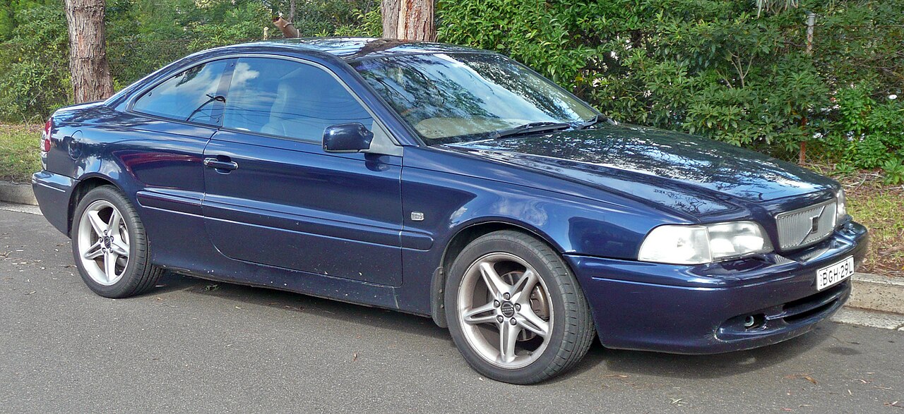
The first-generation Volvo C70 (2001) is a two-door car available as a fixed-roof Coupe or soft-top Convertible. The original Volvo handbook identifies two fuse boxes in the engine compartment: a main high-current block with 14 fuses and four relay locations, and a separate 40-position supplementary fuse holder.
The complete 2001 model-year guide below retains 58 individually documented positions (14 main fuses, four relays, 40 supplementary entries), including spare positions and self-resetting circuit breakers. It is not interchangeable with the C70 II or the different 2002-2005 fuse charts. In 2001, main position 9 is unused and the supplementary list ends at 40.
Where are the Volvo C70 2001 fuse boxes?
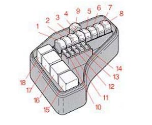
Main relay and fuse box: under a plastic cover in the engine compartment. It protects high-current supplies for the starter, headlamps, ABS/STC and engine control systems. Because major current feeds are involved, Volvo recommends suitable workshop procedures when diagnosing or replacing main power fuses.
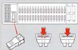
Supplementary fuse box: also in the engine compartment, behind its own cover. Its lid carries a fuse description and may hold spare inserts and a fuse puller. It protects the 12 V outlet, headlights, wipers, audio, cabin lighting, locking and electrically operated accessories. A fuse panel under the glovebox is associated with later C70 II designs, not this first-generation 2001 guide.
Volvo C70 I 2001 main fuses 1-14
The main fuse list documents the cooling fan, starter, engine controllers, ABS/STC and the headlamp feed. Position 4 (50 A) is an ABS/STC feed and position 5 (50 A) supplies the main headlamp circuit. Position 12 (15 A) includes fuel pump and injection control. Manufacturer documentation leaves main position 9 unoccupied.
| Position | Rating [A] / type | Protected circuit / function |
|---|---|---|
| 1 | 60 | Engine radiator cooling fan |
| 2 | 50 | First main power feed to supplementary fuse box |
| 3 | 50 | Main starter circuit supply |
| 4 | 50 | ABS and Stability and Traction Control (STC), if equipped |
| 5 | 50 | Main headlamp supply |
| 6 | 60 | Second main supply to supplementary fuse box |
| 7 | 50 | Third main supply to supplementary fuse box |
| 8 | 60 | Engine and automatic transmission controllers |
| 9 | – | Unused in the original Volvo C70 2001 fuse list. Do not add a fuse using a later-year reference |
| 10 | 10 | Ignition switch, engine controller and automatic transmission module |
| 11 | 15 | Air-conditioning relay and fuel system circuits |
| 12 | 15 | Fuel pump, injectors and engine control module |
| 13 | 15 | Petrol engine ignition system |
| 14 | 20 | Emissions control equipment |
Volvo C70 2001 relay positions 15-18
Numbers 15-18 identify relay slots rather than ordinary blade fuses. Relay 15 is the system relay, 17 the starter relay and 18 the air-conditioning relay; 16 is unused in this manufacturer’s chart. Do not treat a relay as an ampere-rated fuse.
| Position | Rating [A] / type | Protected circuit / function |
|---|---|---|
| 15 | Relay | System relay, as described in the 2001 Volvo handbook |
| 16 | Relay | Unused relay position |
| 17 | Relay | Starter relay |
| 18 | Relay | Air-conditioning relay |
Volvo C70 2001 supplementary fuse box 1-40
The supplementary fuse box retains all forty numbered positions. In this particular 2001 layout, 12 V outlet/cigarette lighter is position 30 (15 A), OBD II-related control is position 5 (15 A), brake lamps position 11 (10 A), and windscreen wiper/washer circuits position 34 (25 A).
| Position | Rating [A] / type | Protected circuit / function |
|---|---|---|
| 1 | 10 | Luggage compartment electric release solenoid |
| 2 | 10 | Rear fog lamp and trailer electrical connector |
| 3 | 10 | Central locking |
| 4 | 10 | Immobiliser, ABS and automatic gearbox shiftlock |
| 5 | 15 | Air-conditioning control supply and OBD II diagnostic connector |
| 6 | 20 | Secondary central-locking circuit |
| 7 | 15 | Factory audio system |
| 8 | 15 | Immobiliser, onboard computer and light switch |
| 9 | 30 | Factory audio amplifier |
| 10 | 10 | Remote-controlled central locking |
| 11 | 10 | Brake lights |
| 12 | 30 | Additional factory audio system circuit |
| 13 | 15 | Hazard flashers, headlamp flash, turn signals and remote central locking |
| 14 | 40 | Heated rear window and exterior mirrors; the 2001 handbook specifies 40 A |
| 15 | 10 | Interior, door, boot, glovebox and passenger mirror lighting, and seatbelt reminder |
| 16 | 30 | Electric aerial, original equipment accessories and trailer wiring |
| 17 | 20 | Front fog lamps, if fitted |
| 18 | 10 | Ignition key reminder and headlamp relay |
| 19 | 15 | Left high-beam headlamp and selected accessories |
| 20 | 15 | Right high-beam headlamp and dashboard indicator |
| 21 | 15 | Left dipped-beam headlamp |
| 22 | 15 | Right dipped-beam headlamp |
| 23 | 10 | Left front/rear position lamps, registration plate light and trailer connector |
| 24 | 10 | Right front/rear position lamps and trailer connector |
| 25 | – | Unused position |
| 26 | 15 | Headlamp switch |
| 27 | 15 | Reversing lamps and direction indicators |
| 28 | 25 | Heated front seats, if equipped |
| 29 | 10 | Rear window/mirror heating, seat belt reminder, cruise control, bulb-out sensor, accessories and shiftlock |
| 30 | 15 | 12 V accessory power outlet / cigarette lighter |
| 31 | 25 | Cabin heater and air-conditioning blower |
| 32 | 10 | Audio, ECC climate control, Coupe electric sunroof and instrument illumination |
| 33 | – | Unused position |
| 34 | 25 | Windscreen wipers, washer and horn circuits |
| 35 | 10 | Accessories, optional Coupe sunroof, driver’s mirror light, interior lighting and optional auto-dimming mirror |
| 36 | 15 | Seatbelt warning reminder |
| 37 | AUT/CB | Self-resetting circuit breaker for electric windows, sunroof and mirrors; not a regular blade fuse |
| 38 | – | Unused in the original 2001 Volvo C70 list |
| 39 | AUT/CB | Self-resetting circuit breaker for driver’s electric seat |
| 40 | AUT/CB | Self-resetting circuit breaker for passenger electric seat |
Important: supplementary positions 37, 39 and 40 are labelled AUT/CB automatic circuit breakers, protecting power windows/roof/mirrors or electric seats. They are not conventional fuses and must not be bypassed or replaced with standard blade fuses.
Volvo C70 2001 cigarette lighter, headlights, wipers and roof
Cigarette lighter / 12 V socket: supplementary 30 (15 A). OBD II diagnostics: supplementary 5 (15 A). Brake lights: supplementary 11 (10 A). Heated rear window and mirrors: supplementary 14 (40 A), as stated in the 2001 handbook.
Left/right high beams: supplementary 19 and 20 (15 A each). Left/right dipped beams: 21 and 22 (15 A each). The high-current main headlamp feed at position 5 is a different circuit from these individual lamp fuses.
Wipers and washers: supplementary 34 (25 A) also includes certain horn functions. Engine no-start: main 12 (15 A) supplies fuel pump/injection circuits and main 13 (15 A) the ignition system; further testing is required before replacing a fuel pump or ECM.
Electric windows and Coupe sunroof: supplementary breaker 37 (AUT/CB). Driver’s and passenger power seats: breakers 39 and 40 respectively. A jammed window or seat mechanism can cause a breaker to trip; do not bridge the contacts.
2001 Coupe versus Convertible and other Volvo models
The Coupe may have an optional electric sunroof while the Convertible uses a folding soft top with separate operating mechanisms. Fuse labels mentioning the Coupe’s sunroof do not establish the hydraulic or control supply for every Convertible; verify the specific convertible-top technical diagram.
For the related model years, see the Volvo C70 1999-2000 Coupe and Convertible fuse guide and the Volvo C70 2002 fuse diagrams. Differences in the roof circuits and ampere ratings must be checked for each year. For a different early Volvo generation, see the Volvo XC90 2003 fuse guide and Volvo XC90 2004 reference. They use different numbering and fuse locations and cannot be used as substitutes for the C70.
Volvo C70 I 2001 fuse box FAQ
Which fuse supplies the cigarette lighter?
Supplementary fuse 30 (15 A), in the engine-compartment supplementary box.
Is main fuse 9 missing?
No. It is described as unused in the original 2001 Volvo C70 reference.
Where is the wiper fuse?
Supplementary fuse 34, rated 25 A.
What are AUT/CB positions 37, 39 and 40?
Automatic circuit breakers for electric windows, roof/mirrors and electric seats, not ordinary blade fuses.
Where is the main fuse for the starter?
Main engine-bay fuse position 3 (50 A) is the primary starter-related supply in this chart; relay 17 is the separate starter relay.
Never install a higher-rated fuse to mask an electrical fault; identify the damaged circuit instead.
Volvo C70 model year 2001 owner’s handbook, fuse section (pp. 89-91). Featured Coupe photograph: OSX, Wikimedia Commons, public domain.