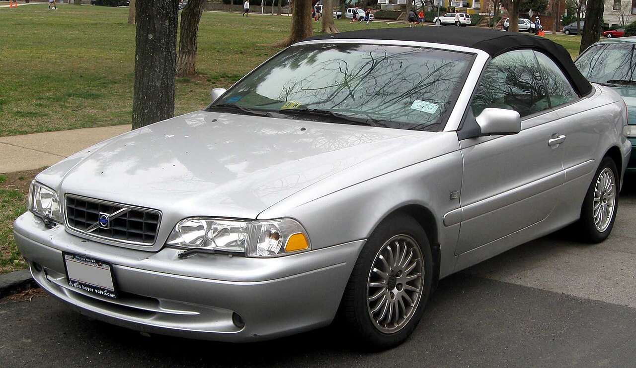
The first-generation Volvo C70 Convertible (2003-2005) has an electrically operated fabric soft top, not the folding hard roof used by the later C70 II. Its two fuse holders are located in the engine compartment: a main block with 14 fuses and four relays, and a supplementary box listing 42 positions including automatic circuit breakers.
This guide preserves 60 documented positions and both original schematic drawings. Important variations include supplementary audio position 7: 15 A for 2003 or 20 A for 2004. For 2005, verify the actual fuse and vehicle’s original handbook instead of applying either value universally.
Where are the Volvo C70 2003-2005 fuse boxes?
Main relay/fuse box: under a plastic cover in the engine compartment. This unit protects the starter, radiator fan, ABS/STC, headlamp main feed and engine control system. The manufacturer recommends qualified diagnosis when a high-current main fuse has blown.
Supplementary fuse box: under its own cover nearby in the engine compartment. Its smaller fuses serve the radio, cigarette lighter, wipers, washers, lights, power windows and convertible roof equipment. Automatic circuit breakers are different from standard blade fuses and must not be bypassed.
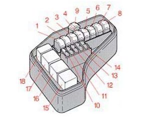
Volvo C70 2003-2005 main fuse box 1-14
The main panel includes position 4 (50 A) for ABS/STC, position 9 (60 A) for power windows, position 12 (15 A) for fuel pump/injection electronics and position 5 (50 A) for the principal headlamp feed. In this source, position 9 is populated and should not be mistaken for an unused slot.
| Position | Rating [A] / type | Protected circuit / function |
|---|---|---|
| 1 | 60 | Electric engine cooling fan |
| 2 | 50 | First main power feed to supplementary fuse box |
| 3 | 50 | Starter supply |
| 4 | 50 | Anti-lock Braking System (ABS) and Stability/Traction Control (STC) |
| 5 | 50 | Main front headlamp supply |
| 6 | 60 | Second main feed to supplementary fuse box |
| 7 | 50 | Third main feed to supplementary fuse box |
| 8 | 60 | Engine and automatic transmission control modules |
| 9 | 60 | Main left and right electric window supply; the position is populated, not unused |
| 10 | 10 | Ignition switch and engine/transmission electronics |
| 11 | 15 | Air-conditioning relay and selected fuel system circuits |
| 12 | 15 | Fuel pump, injectors and Engine Control Module (ECM) |
| 13 | 15 | Petrol engine ignition circuit |
| 14 | 20 | Exhaust emissions control system |
Volvo C70 2003-2005 main relays 15-18
Positions 15-18 are relay sockets, not additional ordinary fuses. Position 15 is described as the system or cooling-fan relay according to the relevant version, position 17 is the starter relay, position 18 the A/C relay, and position 16 is unused in the basic chart. Confirm the relay identifier against the actual housing.
| Position | Rating [A] / type | Protected circuit / function |
|---|---|---|
| 15 | Relay | System / cooling fan relay; consult the specific relay-block diagram for the fitted version |
| 16 | Relay | Unused relay position in standard equipment |
| 17 | Relay | Starter relay |
| 18 | Relay | Air-conditioning relay |
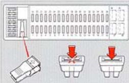
Volvo C70 2003-2005 supplementary fuse box 1-42
The secondary panel protects the 12 V cigarette lighter on position 30 (15 A), OBD II diagnostic supply at position 5 (15 A), brake lamps at position 11 (10 A), and front wipers/washers at position 34 (25 A). The rear-window/mirror heater is listed under position 14 (40 A) in this source.
| Position | Rating [A] / type | Protected circuit / function |
|---|---|---|
| 1 | 10 | Electric tailgate release solenoid and switch |
| 2 | 10 | Rear fog lamp and trailer electrical connectors |
| 3 | 10 | Central door locking |
| 4 | 10 | Immobiliser, ABS and automatic gear selector shiftlock |
| 5 | 15 | Climate control and OBD II diagnostic connector |
| 6 | 20 | Separate central-locking supply |
| 7 | 15 (2003) / 20 (2004) | Factory audio system, 15 A in 2003 and 20 A in 2004; check individual 2005 specification |
| 8 | 15 | Immobiliser, trip computer and lighting switch |
| 9 | 30 | Factory audio amplifier |
| 10 | 10 | Remote control central locking |
| 11 | 10 | Brake lamps |
| 12 | 30 | Main power to selected factory audio equipment |
| 13 | 15 | Hazard lights, headlamp flash, central locking and indicators |
| 14 | 40 | Heated rear window and exterior mirrors |
| 15 | 10 | Cabin, boot and glovebox lights, open-door and seatbelt warnings and window power |
| 16 | 30 | Electric aerial, trailer wiring, accessories and optional CD changer |
| 17 | 20 | Front fog lamps, if fitted |
| 18 | 10 | Ignition key reminder and headlamp relay |
| 19 | 15 | Left main beam and optional accessories |
| 20 | 15 | Right main beam and indicator warning lamp |
| 21 | 15 | Left dipped-beam headlamp |
| 22 | 15 | Right dipped-beam headlamp |
| 23 | 10 | Left front and rear position lamps, number plate illumination and trailer power |
| 24 | 10 | Right position and rear lamps, number plate illumination and trailer power |
| 25 | – | Unused position in standard configuration |
| 26 | 15 | Headlamp switch and lighting controls |
| 27 | 15 | Reversing lamps and direction indicators |
| 28 | 25 | Heated front seats, if fitted |
| 29 | 10 | Heated rear window and mirrors, shiftlock, cruise control, seatbelts, blown-bulb warning and convertible soft-top controls |
| 30 | 15 | 12 V accessory socket and cigarette lighter |
| 31 | 25 | Cabin heater and air-conditioning blower motor |
| 32 | 10 | Audio, ECC automatic climate control, fabric roof electronics, boot lock and instrument illumination |
| 33 | – | Unused position |
| 34 | 25 | Windscreen wipers, washer pumps and horn |
| 35 | 10 | Accessories, convertible roof controls, driver mirror and interior lamps and optional auto-dimming mirror |
| 36 | 15 | Airbag Supplemental Restraint System (SRS) electronics |
| 37 | AUT/CB | Automatic circuit breaker for electric windows and mirrors, not a standard replaceable fuse |
| 38 | AUT/CB | Automatic circuit breaker position without a separately identified consumer in the basic chart |
| 39 | AUT/CB | Automatic circuit breaker for driver power seat |
| 40 | AUT/CB | Automatic circuit breaker for passenger power seat |
| 41 | AUT/CB | Additional automatic circuit breaker for driver power seat in central electrical unit, as identified by this source |
| 42 | AUT/CB | Additional automatic circuit breaker for passenger power seat in central electrical unit, as identified by this source |
The final entries 37-42 use AUT/CB automatic circuit breaker designations rather than ordinary ratings. The table keeps the particular source’s assignment of 41 and 42 to additional power-seat protection in the central electrical unit, rather than copying roof-breaker labels from the separate 2002 model-year reference.
Differences between Volvo C70 2003, 2004 and 2005
Audio fuse 7: 15 A in the 2003 manufacturer’s reference but 20 A in the 2004 reference. For a 2005 vehicle, check its specific installed fuse and original cover label rather than selecting one of these values by guesswork.
Convertible roof: soft-top electrical circuits can include supplementary positions 29, 32 and 35 (10 A each), but the actual roof mechanism, sensors and overload devices require model-specific technical documents. Do not assume all automatic-breaker functions are identical across 2001-2005.
Earlier models are covered individually in our Volvo C70 2002 fuse guide and Volvo C70 2001 fuse diagram. The different roof protection, power-window and infotainment assignments must not be interchanged.
Which fuse should I check for common Volvo C70 issues?
Cigarette lighter or 12 V socket: supplementary 30 (15 A). OBD II diagnostic connector: supplementary 5 (15 A). Brake lights: supplementary 11 (10 A). Front windscreen wipers and washers: supplementary 34 (25 A).
Audio system: supplementary 7 (15 A in 2003, 20 A in 2004); supplementary 9 (30 A) supplies a factory amplifier. A radio that switches on with no sound may indicate the amplifier circuit rather than the radio itself.
Convertible roof: supplementary 29, 32 and 35 (10 A each) may supply associated control and warning functions. Check battery voltage and all manufacturer-specified safety conditions before operating a stalled roof, and do not force the hydraulic or locking system.
Power windows: main 9 (60 A), with additional supplementary automatic breaker 37. Fuel pump and engine electronics: main 12 (15 A) and ignition protection 13 (15 A). A non-starting engine needs diagnosis beyond these fuses.
Headlamps: supplementary 19 and 20 (15 A each) protect left/right high beams; 21 and 22 (15 A each) protect left/right dipped beams. Heated rear window and exterior mirrors: supplementary 14 (40 A) in this chart.
Volvo C70 2003-2005 fuse box FAQ
Where is the cigarette lighter fuse?
Supplementary engine-bay fuse 30 (15 A).
Does the radio use the same amperage in 2003 and 2004?
No. Supplementary fuse 7 is 15 A in 2003 and 20 A in 2004; confirm the individual 2005 specification.
Which fuse supplies electric windows?
Main position 9 (60 A) in the documented Convertible layout, with automatic-breaker protection in the supplementary panel.
Where are the supplementary fuse boxes?
Both main and supplementary protection blocks are under the bonnet on the first-generation C70.
Can I use a second-generation C70 fuse layout?
No. The Volvo C70 II (2006-2008) has a folding hardtop and a different fuse box architecture. Other second-generation layouts are described for 2009 and 2010-2013.
Replace ordinary fuses only with the correct printed rating and type. Repeated failures and overloaded automatic breakers require circuit diagnosis, not bridges or larger fuses.
Year-specific Volvo C70 2003-2004 handbooks and related 2003-2005 electrical charts; original diagrams and public-domain featured convertible photograph preserved from the Polish article.